L404F,T,V PRESSURETROL
®
CONTROLLERS
3
71-2429—06
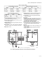
Table 2. Conversion Table.
Table 3. Switch Ratings (Amperes).
Pressure Sensing Element:
Stainless steel diaphragm (140
to 2070 kPa models) has brass bellows.
Maximum Ambient Temperature:
66°C (150°F). Also, refer
to note under Mounting.
Adjustment Means:
Screws on top of control case. Scales are
marked in psi or kPa.
Mounting Means:
1/4 inch-18 NPT connection on diaphragm
assembly; or surface mounts using holes in back of case.
Dimensions:
See Fig. 1.
Switching Action:
Snap switch breaks R-B (closes R-W) on
pressure rise. Make-on-rise devices omit terminal B.
Grounding Means:
Ground screw terminal marked with a
circled ground symbol.
Accessories:
50024585-001 Brass Steam Trap. (Please refer to the applica-
ble Equipment/Application Standards for compliance.)
14026 Steel Steam Trap. (Please refer to the applicable Equip-
ment/Application Standards for compliance.)
118023 Steel Steam Trap for BSPT Models.
33312B Knurled Knob—fits on top of adjusting screws.
4074BWJ Range Stop—range stop screw, Part No. 107194,
and wrench, Part No. 23466, to limit setpoint range.
Approvals:
Underwriters Laboratories Inc. Listed: file no. MP466, vol. 10,
guide no. MBPR.
Canadian Standard Association certified: file no. LR1620,
guide no. 400E-0.
Fig. 1. L404F,T,V approximate dimensions in inches (millimeters in parentheses).
Operating Range Conversions
Subtractive Differential Conversions
kg/cm
2
kPa
psi
kg/cm
2
kPa
psi
0.1 to 1.05
15 to 100
2 to 15
0.15 to 0.4
15 to 40
2 to 6
0.4 to 3.5
35 to 350
5 to 50
0.4 to 1.0
40 to 100
6 to 14
0.7 to 10.0
70 to 1035
10 to 150
0.7 to 1.6
70 to 150
10 to 22
1.5 to 20.0
140 to 2070
20 to 300
1.5 to 3.5
150 to 300
20 to 50
Switch State
120 Vac
240 Vac
Full Load
8.0
5.1
Locked Rotor
48.0
30.6
3-3/4
(95)
1-1/16 (27)
13/16 (21)
1-3/16
(30)
HOLE FOR
1/2 INCH
CONDUIT
DIFFERENIAL
ADJUSTMENT
SCREW
1-1/2 (38)
2-1/8 (54)
M19635B
1-13/16
(46)
4-1/2 (115)
4-11/32 (111)
1-61/64 (50)
1-15/16 (49)
3/16 X 11/32
(5 X 9)
KNOCKOUT
MAIN SCALE
ADJUSTMENT
SCREW
1/4 –18 NPT
CLEAR
PLASTIC
COVER
3-7/8
(99)
2-3/4 (70)
3-1/4 (83)
DIMENSION
"A"
(SEE TAB)
1
1
1 15 TO 100 kPa (2 TO 15 PSI) SCALE MODELS ONLY.
PSI
RANGE
2 TO 15
5 TO 50
10 TO 150
20 TO 300
DIMENSION
"A"
123
126
126
146

