P7810A-D PRESSURETROL® CONTROLLER
5
65-0268—1
3.
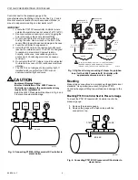
Mount the P7810 Controller and pressure gauge on the
end of the tee.
4.
If not convenient to mount the P7810 Controller next to
the pressure gauge, install a siphon loop in the
manufacturer provided fitting.
5.
If there is no fitting, mount the siphon loop at the boiler
manufacturer recommended location.
6.
Attach the P7810 Controller directly to the siphon loop.
7.
Level the P7810 Controller after the installation.
NOTE: The P7810C,D models require 1/2 in. (13 mm)
mounting either directly or on a siphon loop.
Remote Location Mounting
Excessive vibration at the boiler can damage the P7810
Controller electronics.
1.
Mount the P7810 Controller at a remote location to
eliminate vibration problems.
2.
Make sure that all piping from the boiler is suitable to
the application and solidly mounted.
3.
Pitch the piping properly to drain the condensate back
to the boiler.
4.
Mount the siphon loop between the remote piping and
the P7810 Controller.
5.
Level the P7810 Controller after the installation.
WIRING
WARNING
Electrical Shock Hazard.
Can cause severe injury, death or property
damage.
Disconnect the power supply before wiring. More than
one power supply disconnect may be involved.
All wiring must comply with applicable electrical codes,
ordinances and regulations. Use NEC Class 1 line voltage
wiring.
For normal installation, use moisture-resistant No. 14 wire
(maximum size allowed) suitable for at least 167°F (75°C) or
194°F (90°C) for Flame Safeguard Primary Controls.
Use shielded wire for 4 to 20 mA modulating output and
terminate the shield to earth ground. Do not run these wires in
the same conduit as high voltage ignition wires.
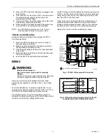
All P7810 Pressuretrol® Controllers have terminal screws and
27/32 in. (22 mm) holes in both sides for conduit, cables and
wiring. Remove the top cover by loosening the screw at the
top of the P7810 Controller case.
Follow the burner or boiler manufacturer wiring diagram, if
provided. Make sure the loads do not exceed the contact
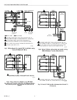
ratings in the Specifications section. See Fig. 5 for terminal
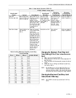
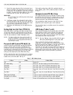
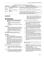
locations and Fig. 6 through 10 for typical wiring hookups.
Replace the front cover after completing the wiring.
Fig. 5. P7810C,D Pressuretrol® Controller.
Fig. 6. Firing rate wiring diagram using 4 to 20 mA
controller and Series 70 Modutrol® Motor.
1/4 IN. NPT
1/4 IN. NPT
1/2 IN. NPT
STEAM
PRESSURE
CONTROL
SENSOR
STEAM
PRESSURE
HIGH LIMIT
CONTROL
SENSOR
NPT
M11895D
1 USE COPPER CONDUCTORS ONLY
1
1
+mA
-mA
OUTPUT
L2
GND
ALARM
LINE VOLTAGE
L1
(MODULATE)
PROGRAMMER WIRING
HIGH FIRE
COMMON
MODULATE
LOW FIRE
F
-
–
+
MODUTROL®
MOTOR
P7810
CONTROLLER
M17130A
+

