P7810C,D PRESSURETROL
®
CONTROLLER
65-0235—1
5
Fig. 4. Wiring diagram for typical P7810
installation using Series 90 Modutrol® Motor.
Replace the front cover after completing the wiring.
Wiring for the 4 to 20 mA operation is shown in Fig. 5.
OPERATION
The P7810C,D uses integral electronic pressure sensors to
sense pressure at the inlet. The sensed pressure and input
setpoint energize a separate relay for the control function, a
separate relay for the limit function and output a 4 to 20 mA
modulation signal for the modulation function. A more detailed
explanation of the functions of the devices follows.
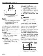
The P7810C and D include an internal steam pressure
manifold (see Fig. 6) which consists of two 1/4 in. NPT
(1/4 NPS) connections to the steam pressure header. The
internal steam pressure manifold provides separate sensing
elements and operating switches. The sensors provide:
a. Steam pressure control (on-off/modulate—P7810C
only). The function of this sensor is to shut off the fuel
supply to the boiler or system through the Flame
Safeguard control when the steam pressure reaches a
preset operating pressure (on-off) setpoint. In addition,
the P7810C provides a 4 to 20 mA output current that
adjusts to match firing rate to steam pressure changes.
b. Steam pressure safety high limit control causes a safety
shutdown and lockout when the steam pressure
reaches a preset safety high limit setpoint.
Fig. 5. Firing Rate Wiring Diagram using P7810C,D Pressuretrol® Controller and Series 90
Modutrol Motor with Manual Position Potentiometer and Auto-Manual Switch.
M11892A
7800 SERIES
PROGRAMMER
MODUTROL®
MOTOR
P7810 PRESSURETROL®
CONTROLLER
HIGH
COMMON
237
OHM
66.5
OHM
MODULATION
LOW
9K1
9K2
8K2
8K1
L2
4
6
N.O.
COM
L2
L1
120 VAC LINE
VOLTAGE
120 VAC LINE
VOLTAGE
7800 SERIES SHOWN. REFER TO SPECIFICATIONS PACKED WITH THE
PROGRAMMER FOR WIRING OF OTHER PRIMARY SAFETY CONTROLLERS.
MODUTROL® MOTOR MUST BE MODUTROL III OR MODUTROL IV,
SERIES 90, ELECTRONIC BALANCE RELAY TO OPERATE AS SHOWN.
PART OF 4074EDC OR 4074EED BAG ASSEMBLY ORDERED SEPARATELY.
MAKE SURE LIMITS VOLTAGE SUPPLY IS CONNECTED TO COM TERMINAL.
1
2
3
3
3
4
4
1
2
12
13
15
14
R
B
W
–
+
4 TO 20mA
LIMITS
FIELD WIRING
2K1 1K1
DEVICE WIRING
MANUAL
S443A AUTO/MANUAL CONTROL WITH INTERNAL
135-OHM POTENTIOMETER.
PART OF 4074EDC BAG ASSEMBLY OR 4074EED
BAG ASSEMBLY, ORDERED SEPARATELY.
MAKE SURE LIMITS VOLTAGE SUPPLY IS
CONNECTED TO COM TERMINAL.
AUTOMATIC
7800 SERIES PROGRAMMER
HIGH FIRE
COMMON
237
OHM
66.5
OHM
MODULATE
LOW FIRE
9K1
9K2
8K2
8K1
12
6
13
15
14
W
W
R
R
B
B
W
R
B
–
+
L1
2K1
1K1
NO
COM
L2
MODUTROL®
MOTOR
P7810 CONTROLLER
LIMITS
120V
LINE
VOLTAGE
M11894A
1
1
2
2
2
3
3


