2 of 12
List of Contents
Document 800-08279, Revision A
February 2011
© Honeywell International. All rights reserved.
• No user-serviceable parts. Installation and servicing should only be performed by
qualified personnel.
• Route all power-limited (low voltage) wiring at least 1/4” (6.35 mm) away from any
non-power limited wiring.
NOTE:
The wires going from the battery to the power supply are
non-power-limited
. All the wires that go from the power supply to the other components in the
enclosure (except the battery) are
power-limited
.
• Backup battery 12V, 7 AH sealed lead-acid maintenance-free battery, 712BNP or
equivalent.
3 List of Contents
• Power Supply Assembly (1)
• Cable Assembly 12VDC Power and Battery connections (1)
• Cable Assembly AC and Battery Fail connections (1)
• Cable Assembly AC Power Inlet and LED Power Indicator (1)
• Cable Assembly Ground Plate to Chassis (1)
• Power Supply Mounting Plate (4 keyholes) (1)
• Machine Screw 8-32x5/16” Ground Wire to Plate (1)
• Kep Nut 8-32 Ground Wire to Plate (1)
• Machine Screw M3x0.5, 6mm Power Supply to Mounting Plate (4)
• Installation Instructions (1)
• IEC Power Cord (1)
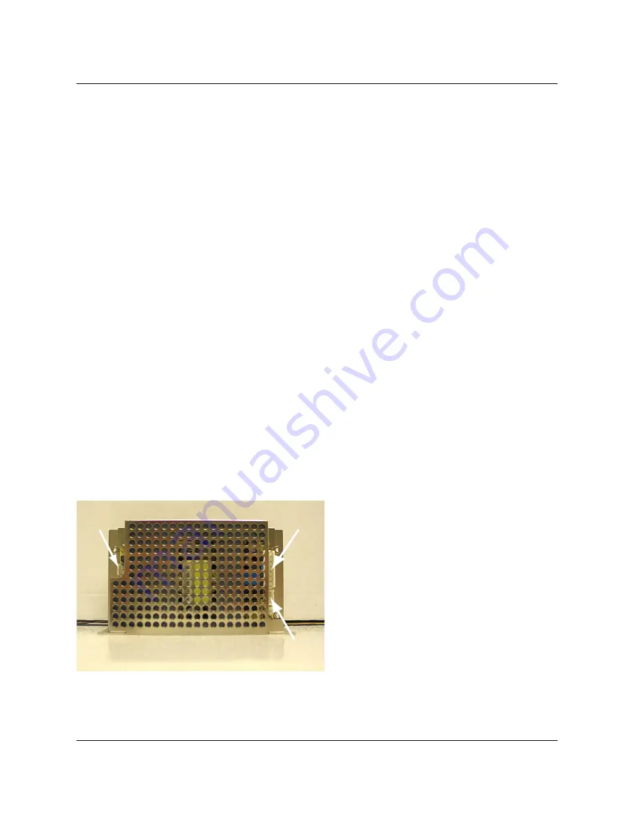
4 Cable Assembly Connections
The power supply has three pin connectors (CN1, CN2, and CN3) to which you need to connect three
cable assemblies, as shown below:
Figure 1: Power Supply Pin Connectors
CN1
CN2
CN3
3 Pin Connectors


