C7012A,C,E,F,G SOLID STATE PURPLE PEEPER® ULTRAVIOLET FLAME DETECTORS
9
60-2398-17
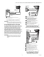
Fig. 9. Splicing leadwires in a junction box.
IMPORTANT
Do not run the flame detector wiring in the same
conduit with high voltage ignition transformer wires.
Connecting Detectors in Parallel
For a flame that is difficult to sight, using two parallel C7012
Flame Detectors reduces nuisance shutdowns. If only one of
the parallel detectors loses the flame signal, the other will
indicate the presence of the flame and keep the burner
running. When two parallel C7012E or F Detectors (with
self-checking shutters) are used, a flame-simulating failure in
either detector system causes the burner to shut down. Two
C7012E or F Detectors can be connected in parallel to the
same terminals on 120 volt flame safeguard controls. To avoid
exceeding the rating of the solid-state shutter switch in the
R7247C, R7747C, R7847C Flame Signal Amplifier, do not
connect more than two C7012E or F Detectors in parallel.
IMPORTANT
Voltage and frequency rating of the C7012 must
match the power supply of the flame safeguard
control.
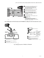
Fig. 10. Wiring diagram for C7012A,C, or G
Detectors with rectification type, flame
safeguard primary and programming controls.
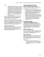
Fig. 11. Wiring diagram for C7012E or F
Detectors with R4075C or D (currently
obsolete) Flame Safeguard Controls.
CONDUIT CONTAINING
LEADWIRES SUPPLIED
WITH C7012E
JUNCTION BOX
CONDUIT CONTAINING
F-G LEADWIRES
CONDUIT CONTAINING
POWER AND SHUTTER
LEADWIRES
M20035
CONTROL
CABINET
C7012E
1
1
1
ISOLATE F-G LEADWIRES FROM OTHER LINE VOLTAGE WIRING
BY A MINIMUM OF 2 INCHES.
YELLOW/GREEN
YELLOW
BLACK
M9371
G
C7012A,C,G
1
FLAME SAFEGUARD
CONTROL
TERMINAL STRIP
OR WIRING SUBBASE
1
TWO C7012A,C, OR G DETECTORS CAN BE CONNECTED
IN PARALLEL TO THE SAME TERMINALS.
THE ADDITIONAL YELLOW/GREEN LEADWIRE IS ONLY ON
C7012G MODELS DESIGNED TO MEET DIN OR BGC
REQUIREMENTS; CONNECT THIS WIRE TO A SEPARATE
GROUND TERMINAL ON THE WIRING SUBBASE.
VOLTAGE AND FREQUENCY RATING OF THE C7012A,C, OR G
MUST MATCH THE POWER SUPPLY OF THE FLAME
SAFEGUARD CONTROL.
ON THE BCS7700 CONTROL, THE BLUE WIRE CONNECTS TO
TERMINAL 31, THE YELLOW LEADWIRE TO TERMINAL 29.
( ) IDENTIFICATION LABEL ON LEADWIRES.
2
3
BLUE
F
BLACK
L1
L2
(L2)
(L1)
(POWER
SUPPLY)
2
3
5
4
4
5
BLUE
YELLOW
BLACK
BLACK
M9372
12
11
G
F
10
2A
C7012E,F
2
TERMINAL STRIP
FOR R4075C OR D
IN CABINET
OR ON SUBBASE
1
AN R7247C DYNAMIC SELF-CHECK AMPLIFIER MUST BE
USED WITH AN R4075C OR D.
TWO C7012E OR F DETECTORS CAN BE CONNECTED IN PARALLEL
TO THE SAME TERMINALS ONLY ON 120 VOLT CONTROLS.
REMOVE THE JUMPERS BETWEEN TERMINALS 12 AND F AND
BETWEEN TERMINALS 11 AND 10 (IF THERE ARE JUMPERS), AND
INSTALL A JUMPER BETWEEN TERMINALS 11 AND 3.
VOLTAGE AND FREQUENCY RATING OF THE C7012E OR F MUST
MATCH THE POWER SUPPLY OF THE FLAME SAFEGUARD CONTROL.
( ) IDENTIFICATION LABEL ON LEADWIRES.
2
3
4
1
WHITE
3
WHITE
L1
L2
(POWER
SUPPLY)
4
5
5
3
(L2)
(S)
(L2)
(L1)


