C7012A,C,E,F,G SOLID STATE PURPLE PEEPER® ULTRAVIOLET FLAME DETECTORS
60-2398-17
12
ADJUSTMENTS AND
CHECKOUT
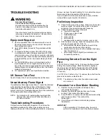
UV Sensor Tube Test
For initial burner lightoff, consult the burner manufacturer
instructions or the instructions for the flame safeguard control.
If the system does not start during the initial burner lightoff,
check the UV sensor tube in the flame detector. If a reddish
glow appears when there is no flame present, replace the UV
sensing tube. When performing this test, make sure there are
no extraneous sources of ultraviolet radiation in the test area
(see Radiation Sources section).
Adjust Detector Sighting
With the flame detector installed and the burner running, adjust
the sighting position of the detector for optimum flame signal.
Most existing Honeywell flame safeguard controls incorporate
a flame current jack on the control flame amplifier or on the
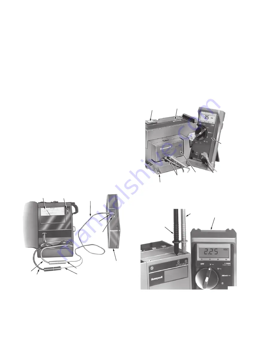
control itself. Measure the flame signal with a volt-ohmmeter
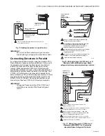
such as the Honeywell W136A Volt-ohmmeter (see Fig. 17). To
measure the flame current (signal), use 196146 Cable
Connector, included with W136A, in conjunction with the meter.
With the W136A (or equivalent) positioned to the zero to 25
microampere scale, connect the meter probes to the two ends
of the cable connector plug (red to red, black to black). Insert
the plug end of the connector plug directly into the flame jack of
the control or control amplifier (see Fig. 17). The W136A Meter
then directly reads the flame signal in microamperes. Refer to
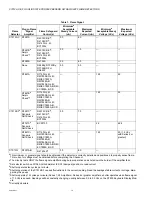
Table 1 for minimum acceptable flame currents.
Fig. 18. Measuring microamp flame signal.
The R7747C and R7847C Amplifiers used with the BCS 7700
and 7800 Series Flame Safeguard controls, respectively, have
a dc voltage flame signal output. For the R7747C Amplifiers, a
volt-ohmmeter with a 20,000 ohm/volt minimum input
impedance and a zero to five or ten Vdc scale is
recommended. It is suggested that a volt-ohm meter with a
minimum sensitivity of one megohm/volt and a zero to five or
ten Vdc scale be used for R7847C Amplifier flame signal
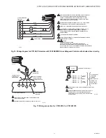
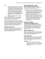
measurements. Measure the flame signal as illustrated in
Fig. 18 and 19. Be careful to make the proper connections of
positive (red) meter lead to positive (+) control jack and
negative (black) meter lead to negative (-) or (-Com) jack with
7800 Series controls. If the BCS 7700 and 7800 Series
controls have the Keyboard Display Module, a zero to five Vdc
voltage displays on the module.
Fig. 19. Measuring voltage flame
signal with BCS 7700 (currently obsolete) controls.
Fig. 20. Measuring voltage flame
signal with 7800 Series controls.
W136A VOLT-
OHMMETER
W136A SELECTOR
SWITCH
196146 METER
CONNECTOR
PLUG
PLUG
PLUG-IN FLAME
SIGNAL AMPLIFIER
FLAME SIGNAL
METER JACK
RED CONNECTOR
BLACK CONNECTOR
BLACK (–) METER LEAD
RED (+)
METER
LEAD
M6532A
RESET
BUTTON
PROGRAM
MODULE
20,000
VOLT-
OHMMETER
BCS 7700 CHASSIS MODULE FOOTMOUNT
METER
PROBES
FLAME
AMPLIFER
M7860
NEGATIVE (-)
METER LEAD
POSITIVE (+)
METER LEAD
ONE MEGOHM
MINIMUM INPUT
IMPEDANCE
METER
M6818


