C7012A,C,E,F,G SOLID STATE PURPLE PEEPER® ULTRAVIOLET FLAME DETECTORS
60-2398-17
4
1 inch NPT internal threads (for mounting) to a 3/4 inch
sight pipe, or to the pipe nipple and tee for connecting an
air supply.
W136A Test Meter (includes 196146 Meter
Connector Plug).
117053 Meter Connector Plug (for older W136A models).
C7012A,E and G:
122748 Quartz Viewing Window, rated for 50 psi
(345 kPa).
124204 Quartz Focusing Lens, rated for 20 psi (137 kPa);
for increasing the detector-sensed ultraviolet radiation.
Flange, aluminum, with 1 inch NPT internal threads for
attaching to sight pipe.
123539 Antivibration Mount.
190105 Water Jacket.
Swivel Mount.
Seal-off Assembly, for seal-off of 3/4 in.
NPT pipe.
204341A UV mirror with 3/4 in. NPT internal threads.
INSTALLATION
When Installing this Product...
1.
Read these instructions carefully. Failure to follow them
could damage the product or cause a hazardous
condition.
2.
Check the ratings given in the instructions and on the
product to make sure the product is suitable for your
application.
3.
Installer must be a trained, experienced flame safeguard
service technician.
4.
After installation is complete, check out product
operation as provided in these instructions.
CAUTION
Equipment Damage Hazard.
Sensing tube can fail to discriminate between
flame conditions.
Change sensing tube after 40,000 hours of
continuous use.
Appliances with burners that remain on continuously for
24 hours or longer should use the C7012E,F Flame Detector
and the R7247C, or R7847C Amplifiers and associated
controls.
WARNING
Electrical shock hazard.
Can cause serious injury or death.
Disconnect power supply before beginning installation
to prevent electrical shock and equipment damage.
More that one disconnect can be involved.
IMPORTANT
1. Do not connect these detectors to non-Honeywell
manufactured controls (primaries, programmers,
multiburner systems, and burner management
systems). Unsafe conditions could result.
2. All wiring must be NEC Class 1 (line voltage).
3. Voltage and frequency of the power supply connected
to this detector must agree with the values marked on
the detector.
4. The detector must be sighted so it does not respond
to ignition spark.
5. On multiburner installations, each detector must
respond only to the flame produced by the burner it is
supervising.
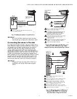
6. Do not connect more than two C7012 Flame
Detectors in parallel.
Proper flame detector installation is the basis of a safe and
reliable flame safeguard installation. Refer also to the burner
manufacturer instructions. Carefully follow the instructions for
the best possible flame detection application.
Basic Requirements
The combustion flames of most carbon-based fuels emit
sufficient ultraviolet radiation to enable the C7012 Solid State
Purple Peeper® Ultraviolet Flame Detector to prove the
presence of a flame in a combustion chamber. The detector is
mounted outside the combustion chamber. Its mounting flange
or union is threaded to one end of a sight pipe inserted through
the wall of the combustion chamber. The ultraviolet sensing
tube in the flame detector sights the flame through the pipe.
When a flame is present, the UV tube in the C7012 senses the
ultraviolet radiation emitted. The C7012 produces a signal that
is sent to the amplifier in the flame safeguard control. The
amplified signal pulls the flame relay into the control to allow
proper operation of the system.
Because it is necessary for the UV sensing tube to actually see
the flame, it is best to locate the detector as close to the flame
as physical arrangement, temperature, and other restrictions
permit. These restrictions are described in detail in the
following paragraphs.
Determine Location
Before beginning the actual installation, determine the best
location for mounting the detector. Carefully consider the
factors discussed in this section before deciding on
the location.
Temperature
Install the C7012 where the ambient temperature (outside the
case) stays within the ambient operating temperature ratings.
To keep the C7012 below its maximum rating, it may be
necessary to add additional insulation between the wall of the
combustion chamber and the detector. A shield or screen can
be added to reflect radiated heat away from the detector. If the
detector continues to get too hot, cooling is necessary. Refer to
the Sight Pipe Ventilation section. A 190105 Water Jacket is
also available for cooling the C7012A,E,G Flame Detectors.
See Accessories.
Vibration
If the C7012 is subject to excessive vibration, use a special
123539 Antivibration Mount for the C7012A,E or G. If you use
this mount, install it before you position and sight the detector.


