16
www.honeywell.com
PW6K1ICE Wiring and Setup
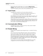
Specifications
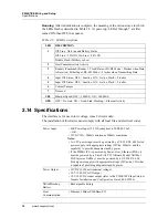
Running:
After initialization is complete, the meaning of the various ways in which
the LEDs flash is described in Table 2-5. At power up, LEDs 2 through 7 are first
turned ON, then OFF, in sequence.
2.14 Specifications
The interface is for use in low voltage, class 2 circuits only.
The installation of this device must comply with all local fire and electrical codes.
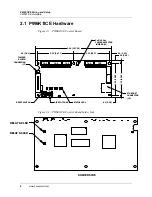
Table 2-5: LED Descriptions
LED
DESCRIPTION
1
Off-Line / On-Line and Battery Status
Off-Line = 20% ON, On-Line = 80% ON
Double Flash if Battery is Low
2
Host Communication Activity
3
Readers (Combined) Reader 1: Clock/Data or D1/D0 Mode = Flashes when Data
is Received, Either Input. RS-485 Mode = Flashes when Transmitting Data
4
Input IN1 Status: OFF = Inactive, ON = Active, Flash = Trouble
5
Input IN2 Status: OFF = Inactive, ON = Active, Flash = Trouble
6
Cabinet Tamper
7
Not used
YEL
Ethernet Speed: OFF = 10Mb/S, ON = 100Mb/S
GRN
OFF = No Link, ON = Good Link, Flashing = Ethernet Activity
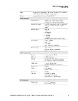
Power Input
• PoE Power Input 12.95W, compliant to IEEE 802.3af
- OR -
• 12VDC 10%, 200mA minimum, 900mA maximum
Notes:
• A +12V power input must be powered by a UL 294/UL 609 Listed
power supply with appropriate ratings (12Vdc, 900mA) and the
capability to provide adequate standby power.
• If the PW6K1ICE is powered by Power-Over_Ethernet (POE), it
must be powered by a Listed (ALVY) Altronix, Model NetWay1
POE Injector. NetWay1 must be powered by a UL 294/UL 609
Listed power supply with appropriate ratings (24Vac/dc, 1.2A) that
is capable of providing adequate standby power.
Power Output
• 12VDC @ 650mA (nominal voltage)
• 10.7-13.0VDC AUX output
• 10.3-12.6VDC reader output (refer to the
PW6K1R1E Input/Output
Module Installation and Configuration Guide
, 800-07986)
SRAM Backup
Battery
• Rechargeable battery
Host
Communication
• Ethernet: 10BaseT/100Base-TX

