background image

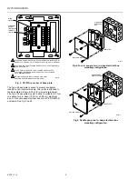
Q7751A ROUTERS 

95-7511—2 2 

1
2
3
4
5
67

89

10

11

12

13

14

15

16

17

18

THREADED SCREW HOLES FOR ATTACHING ROUTER INTERFACE TO 

BASE PLATE. USE 8-32, 3/8 IN. SCREW, Echelon 205-0130-01 OR EQUAL.

0.230 IN. HOLES FOR ATTACHING BASE PLATE TO ELECTRICAL BACK 

BOX OR SUB-PANEL.

0.180 X 0.280 IN. HOLE FOR THE ATTACHING BASE PLATE TO 

ELECTRICAL BACK BOX OR SUB-PANEL. USE 6-32, FLAT-HEAD, 

3/8 IN. MINIMUM SCREW.

WRITING SPACE FOR INSTALLER. USE FINE POINT 

SANFORD SHARPIE MODEL 30001 OR EQUAL.

1

1

1

2

2

2

3

4

4

3

M16382

WIRE

ENTRY

TERMINAL

SCREW,

TIGHTENING

TORQUE 4

LBS. IN.


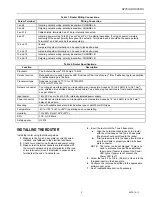
Fig. 3. Q7751A rear view of base plate. 


The Type 2 base plate is keyed to prevent accidental 

insertion of an incorrect module. The router is attached to 

the base plate with two 8-32 x 3/8 in. screws (provided). 

The Type 2 base plate mounts to either a suitable U.S. four 

in. square, two in. deep (10.16 cm x 5.08 cm) electrical 

box, U.S. double gang electrical box or an IP-65 (NEMA 4) 

enclosure. See Fig. 4 and 5. 


ROUTER MODULE

BASE PLATE

4 IN. SQUARE

ELECTRICAL 

BOX

M16384


Fig 4. Four in. square, two in. deep electrical box 

mounting configuration. 


ROUTER MODULE

BASE PLATE

DOUBLE GANG

ELECTRICAL BOX

M16385


Fig 5. Double gang two in. deep electrical box 

mounting configuration. 


Summary of Contents for Q7751A

Page 1: ...CCESS JACKS USE FOR ACCESSTO LONWORKS BUS ROUTER INTERFACE MODEL AND SOFTWARE REVISION NUMBERS PEEL OFF CODE 39 FORMAT BAR CODE OF ROUTER INTERFACE Neuron CHIP ID NUMBER 2 3 3 3 Fig 1 Q7751A Router front plate The router is installed in a Type 2 base plate Wiring connections are presented in Table 1 Specifications for the router are shown in Table 2 Network and power are connected to screw termina...

Page 2: ...IRE ENTRY TERMINAL SCREW TIGHTENING TORQUE 4 LBS IN Fig 3 Q7751A rear view of base plate The Type 2 base plate is keyed to prevent accidental insertion of an incorrect module The router is attached to the base plate with two 8 32 x 3 8 in screws provided The Type 2 base plate mounts to either a suitable U S four in square two in deep 10 16 cm x 5 08 cm electrical box U S double gang electrical box...

Page 3: ...ssible one per channel Input power 16 to 30 Vac or Vdc at 2 0 VA internally isolated power supply Power connector Four black screw terminals non removable wire clamp style Supports 12 to 24 AWG 4 to 0 27 mm 2 daisy chained wire Mounting Use with suitable back plate Electrical box type or wall 35 mm DIN type Temperature 40 to 185 o F 40 to 85 o C operating and non operating Humidity 10 to 95 RH at ...

Page 4: ...or replace faulty power cable Service LED unlit This is the normal state of the LED for a configured module Service LED flashing The module is not configured This is the normal state for a new module Commission the module using the software tool No network communications Network wiring not connected correctly to the module Network cabling shorted open or otherwise damaged Use continuity tester to ...

Reviews: