Q7751A ROUTERS
Home and Building Control
Home and Building Control
Home and Building Control Products
Honeywell Inc.
Honeywell Limited-Honeywell Limitee
Honeywell AG
Honeywell Plaza
155 Gordon Baker Road
Böblinger Straße 17
P.O. Box 524
North York Ontario
D-71101 Schönaich
Minneapolis, MN 55408-0524
M2H 3N7
Phone (49-7031) 637-01
Fax (49-7031) 637-493
95-7510—3 J.D. Rev. 5-99
Printed in U.S.A. on recycled
paper containing at least 10%
post-consumer paper fibers.
www.honeywell.com
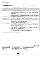
TROUBLESHOOTING
Table 3 contains common troubleshooting symptoms and
possible reasons and actions for repair.
Table 3. Troubleshooting symptoms and solutions.
Symptom Diagnosis
Power LED lit
This is the normal LED state with node powered.
Power LED unlit
Power supply that provides power to the module has lost primary power. Check power supply
outlet for power.
Power wiring not correctly connected to module. Use a meter to check for power on base plate
power terminals.
Input voltage is too low due to excessive load on the power supply that provides power to the
module because of excessively long cabling or power wiring that is shorted. Use a meter to
check for the correct voltage level on the base plate power terminals. Correct wiring length if too
long. Repair or replace faulty power cable.
Service LED unlit
This is the normal state of the LED for a configured module.
Service LED flashing
The module is not configured. This is the normal state for a new module. Commission the
module using the software tool.
No network communications Network wiring not connected correctly to the module.
Network cabling shorted, open, or otherwise damaged. Use continuity tester to check cabling.
Router(s) on network are not commissioned or powered.
Incorrect router channel type installed on channel.
Erratic or improper network
communications
Network wiring not securely connected to base plate terminals. The optimum tightening torque
for a base plate screw terminal is 4 lb/in. (0.5N/m) maximum.
Module not properly seated in the base plate. Make sure the module is pressed firmly into the
base plate and secured with fixing screws.
Use E-Bus Wiring Guidelines, form 74-2865.
Improper network cabling. In some cases, it is possible to correct network communications by
installing the Q7740A or Q7740B repeater in series with the network cabling. In other cases, the
cabling must be replaced with an approved cable.
Too many nodes on a channel. See the appropriate software user guide for channel limitations.
Controllers or devices are connected to the wrong channel of a router. Make sure the correct
types of controllers or devices are connected to the two router channels.
L
ON
W
ORKS
® is a registered trademark of Echelon® Corporation.


