R7195A,B MOTOR POSITIONER
7
63-2582
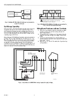
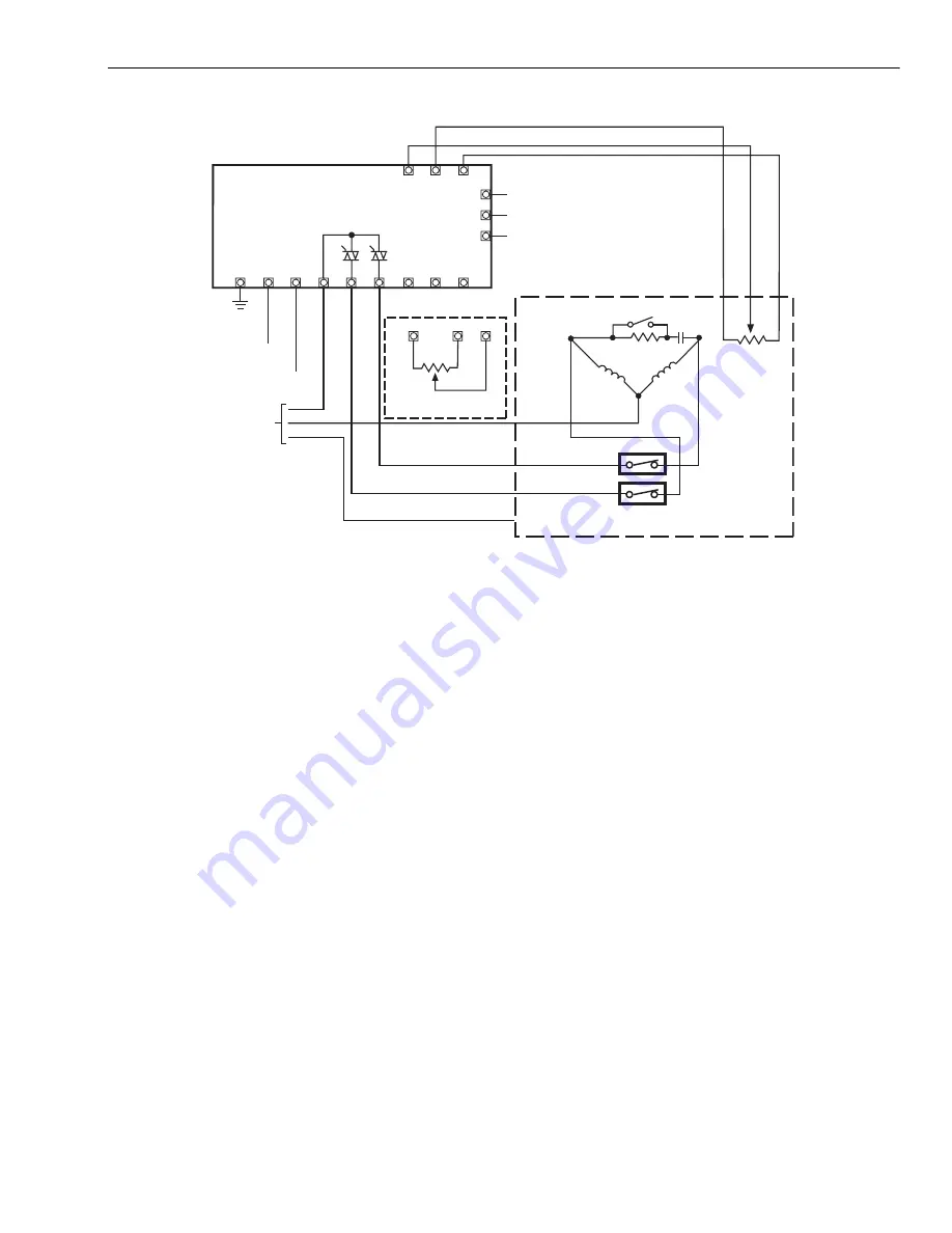
Fig. 9. External wiring diagram.
Heating Application # 1:
When the temperature at the sensor is above the range of the
controller, the controller output will be above the proportioning
range of the controller. For example: the controller output
signal will be less than 4 mA for a 4-20 mA range controller;
motor positioner triac Q3 will fire to drive the motor to the
closed position.
Heating Application # 2:
When the temperature at the sensor is below the range of the
controller, the controller output will be below the proportioning
range of the controller. For example: the controller output will
be greater than 20 mA for a 4-20 mA range controller. Motor
positioner triac Q4 will fire to drive the motor to the open
position.
Heating Application # 3:
When the temperature at the sensor is within the
proportioning range of the controller; Q3 triac will fire as the
sensor temperature rises above the controller setpoint to drive
the motor in the closed direction. Q4 triac will fire as the
temperature at the sensor drops below the controller setpointt
to drive the motor in the open direction.
In each case the motor will move until a new balance point is
reached such that the error voltage between the input signal
and the slidewire signal is zero.
SERVICE AND TROUBLESHOOTING
Calibration Procedure
NOTE: The R7195 Motor Positioner is calibrated at the
factory for a 4-20 mA input signal for the R7195A
and a 135-ohm potentiometer input for the R7195B.
Therefore, do not calibrate the motor positioner
unless the input signal desired is something other
than 4-20 mA (R7195A) or 135 ohms (R7195B).
To calibrate the positioner, refer to Fig. 9.
For the span and zero adjustment check, do the following:
1.
Connect the input source (4-20 mA or 135-ohm
potentiometer) to terminals R, B and W.
2.
Set the input to the minimum value of span. Adjust the
zero potentiometer (P3) to balance out the motor and
the minimum limit.
3.
Set the input to the maximum value of span. Adjust the
span potentiometer (P1) to balance out the motor at the
maximum limit.
Deadband Adjustment
The deadband adjustment (P2) will be set at the mid position
to provide precise control of the process for most process
applications. Some processes may require deadband
adjustment to achieve stable control. Unstable process
conditions may be characterized by:
(P1) SPAN ADJUST
(P2) DEADBAND ADJUST
(P3) ZERO ADJUST
M202794
GROUND
NEUTRAL
HOT
GROUND
R7195 SUPPLY
HOT
ROTOR SWITCH
CCW
CLOSE
CW
OPEN
MOTOR
WINDINGS
Q4
Q3
LIMIT
SWITCHES
NEUTRAL
G
GROUND
MOTOR
SUPPLY
COMMON
4-20 mA INPUT
MOTOR
B
W
R
CW
135-OHM
POTENTIOMETER INPUT
R7195A,B
MOTOR POSITIONER
5
4
6
G
L2
L1
2
3
1
B
W
R
Summary of Contents for R7195A
Page 11: ...11 63 2582 ...


