background image

MacroCel

INTERFACE

BOARD

MOUNTING

TAB (2) 

R7515C MacroCel™ CONTROLLER 

95-7456—1

C5611 

1

2

3

4

5

6

7

8

9

10

11

12

13

14 

R1 

RTD 

D1 

DIG

+10

+10

V1 

VOLT 

R2 

RTD 

D2 

DIG 

V2 

VOLT 

TB1 

R1

R2

TERM V1

TERM V2 

15

16

17

18

19

20

21

22

23

24

25

26

27

28 

R3 

RTD 

D3 

DIG

+10

+10

V3 

VOLT 

R4 

RTD 

D4 

DIG 

V4 

VOLT 

TB2 

R3

R4

TERM V3

TERM V4 

29

30

31

32

33

34

35

36

37

38

39

40

41

42 

R5 

RTD 

D5 

DIG

+10

+10

V5 

VOLT 

R6 

RTD 

D6 

DIG 

V6 

VOLT 

TB3 

R5

R6

TERM V5

TERM V6 

R7 

RTD 

D7 

DIG

+10

+10

V7 

VOLT 

R8 

RTD 

D8 

DIG 

V8 

VOLT 

TB4

47

48

49

50

51

52

53

54

55

56

43

45

46

44 

J1 

J2 

J3 

J4 

R7

R8

TERM V7

TERM V8 

5 7 

5 8 

5 9 

6 0 

+

24 VDC 

TB10 

C1

TO-1

TB5

65

66

67

68

69

70

71

72

61

63

64

62

COM1-2

TO-2

TO-3

COM3-4

TO-4

T1

T2

T1

T2

T1

T2 

O

U

T

P

U

T

R

I

A

2

4

V

A

POWER

LED 

F1

2A

CR2 

TB8

POWER

24VAC T1 

24VAC T2 

J5

CNAP

BUS

JACK 

ON

OFF 

S1 

A

EOL 

J6 

J7 

1

2

1&2

2&3 

J8 

7 4 

+

CNAP

OUT 

IN 

7 6 

TB9 

IN

OUT 

AO—1

TB6 

77

78

RET 

ANALOG 

79

80 

AO—2

RET 

AO—3

TB7 

89

90

RET 

ANALOG 

91

92 

AO—4

RET 

MacroCel

CARD CAGE 

JB1 

INPUTS 

WALL MOD

CONNECTOR J8 

0. 16A MAX 

CNAP

BUS 

0.16A MAX 

83

84

85

86

87

88 

A

C

B

A

C

K1

K2 

OUTPUTS 

95

96

97

98

99

100 

A

C

B

A

C

K3

K4 

SUBPANEL

SUPPORT (2) 

81

82 

AO—5

RET 

93

94 

AO—4

RET 

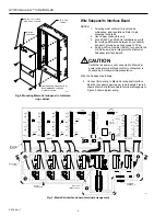
Fig.

 4.

 Macr

oCel typical wiring. 

Summary of Contents for R7515C MacroCel

Page 1: ...ler MacroCel Card Cage Assembly Assembly from carton Check Assembly and report any damage to a Honeywell representative 3 Before installing verify that Ring Cabinet is installed per job drawings Refer to General Purpose Cabinet Installation Instructions 95 7438 for details 4 Installation requires No 10 x 1 2 in sheet metal screws not supplied Six screws are required for full sized subpanel four fo...

Page 2: ...ASE OF INSTALLATION 1 2 3 4 5 6 7 8 9 10 11 12 13 14 R1 RTD D1 DIG 10 10 V1 VOLT R2 RTD D2 DIG V2 VOLT TB1 R1 R2 TERM V1 TERM V2 15 16 17 18 19 20 21 22 23 24 25 26 27 28 R3 RTD D3 DIG 10 10 V3 VOLT R4 RTD D4 DIG V4 VOLT TB2 R3 R4 TERM V3 TERM V4 29 30 31 32 33 34 35 36 37 38 39 40 41 42 R5 RTD D5 DIG 10 10 V5 VOLT R6 RTD D6 DIG V6 VOLT TB3 R5 R6 TERM V5 TERM V6 R7 RTD D7 DIG 10 10 V7 VOLT R8 RTD ...

Page 3: ... 49 50 51 52 53 54 55 56 43 45 46 44 J1 J2 J3 J4 R7 R8 TERM V7 TERM V8 5 7 5 8 5 9 6 0 24 VDC TB10 C1 TO 1 TB5 65 66 67 68 69 70 71 72 61 63 64 62 COM1 2 TO 2 TO 3 COM3 4 TO 4 T1 T2 T1 T2 T1 T2 O U T P U T T R I A C 2 4 V A C POWER LED F1 2A CR2 TB8 POWER 24VAC T1 24VAC T2 J5 CNAP BUS JACK ON OFF S1 A EOL J6 J7 1 2 3 1 2 2 3 J8 3 7 4 5 CNAP OUT IN 7 6 TB9 IN OUT AO 1 TB6 77 78 RET ANALOG 79 80 AO ...

Page 4: ...mounting surface of Assembly flat against Subpanel aligning sides of Assembly with sides of mounting silhouette and top of Assembly approximately 1 in 25 mm above top of mounting silhouette 2 Slide Assembly down simultaneously engaging lower supports and preinstalled mounting tab screws 3 Tighten screws to secure Assembly to Subpanel 4 Connect input output board ribbon cables and power cable to In...

Reviews: