R7515C MacroCel™ CONTROLLER
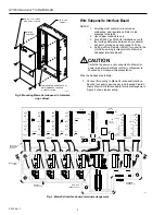
2. Connect C-NAP bus wiring to C-NAP terminal block on
Mount MacroCel Card Cage Assembly
MacroCel per job drawings (Fig. 5).
MacroCel
NOTES:
3
7
4
5
+
+
CNAP
OUT
IN
7
6
TB9
C-NAP
TERMINAL
BLOCK
7
7
RED
YEL
YEL
RED
0.16 MAX
INTERFACE
BOARD
1. Lower edge of Assembly is supported by two supports
on the Subpanel (Fig. 8). Do not force Assembly into
supports. If supports interfere with mounting Assembly,
gain proper clearance by using pliers to bend supports
outward slightly.
2. Two mounting tab screws are factory installed (started)
to aid in mounting the Assembly.
+
+
C5693
Fig. 5. Connecting C-NAP bus wiring to C-NAP terminal
block on MacroCel.
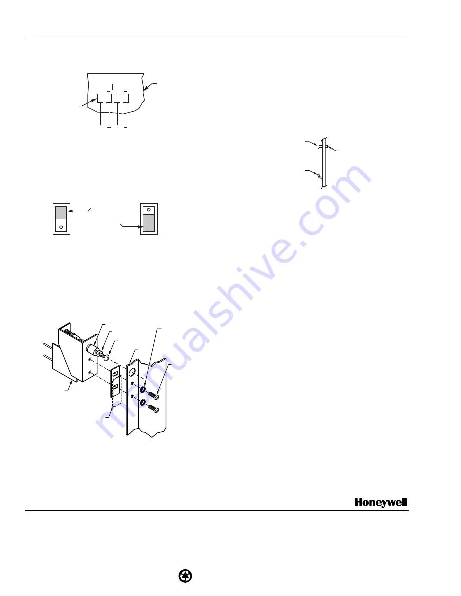
3. When required, activate the EOLR on the MacroCel
Subpanel Interface Board by placing the shorting bar in
Position 1-2 (Fig. 6A). Deactivate the EOLR by placing
the shorting bar in Position 2-3 (Fig. 6B).
A
A
SHORTING BAR
1
1
1 & 2 IN
1 & 2 IN
2
2
SHORTING BAR
2 & 3 OUT
2 & 3 OUT
3
3
EOL
EOL
A. EOLR "IN"
B. EOLR "OUT"
C5687
Fig. 6. MacroCel subpanel interface board EOLR
positions for activation (IN) and deactivation (OUT).
4. Connect line voltage to AC Input Block. Leave power to
MacroCel subpanel OFF until system is checked by a
Honeywell Representative.
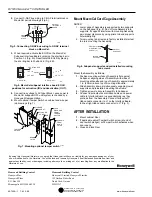
5. Mount optional Tamper Switch on cabinet and wire per
job drawings (Fig. 7).
PREINSTALLED
MOUNTING TAB
SCREW (2)
MacroCel
SUBPANEL
INTEGRAL
SUPPORT
C5689
Fig. 8. Subpanel supports and preinstalled mounting
tab screws.
Mount the Assembly as follows:
1. Position mounting surface of Assembly flat against
Subpanel, aligning sides of Assembly with sides of
mounting silhouette and top of Assembly approximately
1 in. (25 mm) above top of mounting silhouette.
2. Slide Assembly down, simultaneously engaging lower
supports and preinstalled mounting tab screws.
3. Tighten screws to secure Assembly to Subpanel.
4. Connect input/output board ribbon cables and power
cable to Interface Board in sequential order as they
protrude from the Assembly. Connect farthest-left
ribbon cable connector to J1 on the Interface Board,
farthest right ribbon cable connector to J7 (Fig. 3).
LOCK
WASHERS
FROM
TAMPER
SWITCH
PLUNGER
DOOR
LATCH
TAMPER
SWITCH
LOCKNUT
RING
PLUNGER
SCREW
AFTER INSTALLATION
1. Mount cabinet Door.
SCREWS
2. If applicable, adjust Tamper Switch screw (at end of
FROM
door switch plunger) so Tamper Switch activates when
DOOR
LATCH
door opens.
3. Close and lock Door.
C6039
Fig. 7. Mounting optional tamper switch.
Home and Building Control
Home and Building Control
Honeywell Inc.
Honeywell Limited-Honeywell Limitée
Honeywell Plaza
155 Gordon Baker Road
P.O. Box 524
North York, Ontario
Minneapolis MN 55408-0524
M2H 3N7
Printed in U.S.A. on recycled
paper containing at least 10%
95-7456—1 T.M. 2-98
post-consumer paper fibers.
www.honeywell.com
By using this Honeywell literature, you agree that Honeywell will have no liability for any damages arising out of your
use or modification to, the literature. You will defend and indemnify Honeywell, its affiliates and subsidiaries, from and
against any liability, cost, or damages, including attorneys’ fees, arising out of, or resulting from, any modification to the
literature by you.


