background image

R8182D,E,F,H,J COMBINATION PROTECTORELAY™ AND HYDRONIC HEATING CONTROLS

68-0105—2

12

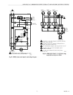
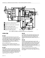
Fig. 17. R8182D and R845A in a typical multiple circulator zoning application.

OPERATION

R8182D

A call for heat by the thermostat pulls in relay 1K, which 

energizes the safety switch circuit and relay 2K to turn on the 

burner. Safety switch starts to heat. If burner ignites within 

safety switch timing, the cadmium sulfide flame detector sees 

flame and the safety switch heater circuit is bypassed. The 

burner operates until the call for heat is satisfied. The 

circulator operates when relay 1K pulls in only if R to W is 

made in the Aquastat¨ limit.

When R to B (low limit) is made by a drop in water 

temperature, it acts as a call for heat, pulling in relay 2K to 

turn on the burner. The circulator cannot operate. See Fig. 11, 

16, 17 and 19.

R8182E

The burner and circulator operate whenever the thermostat 

calls for heat. Relay 2K pulls in. When the cadmium sulfide 

flame detector sees flame, the safety switch heater circuit is 

bypassed, and 2K is held in through 2K1. If temperature rises 

to a high limit setpoint, R to B breaks, shutting off the burner. 

The circulator continues operation under the thermostat 

direction. See Fig. 12, 16, 17 and 20.

R8182F

The thermostat call for heat pulls in relay 2K to turn on the 

burner. When the cadmium sulfide the flame detector sees 

flame, safety switch the heater circuit is bypassed. The 

circulator is independent of the thermostat circuit, being 

controlled only by the Aquastat¨ limit switch. See Fig. 13, 17 

and 20.

R8182H

A call for heat by the thermostat pulls in relay 1K, which 

energizes the safety switch circuit and relay 2K to turn on the 

burner. The safety switch starts to heat. If the burner ignites 

within the safety switch timing, the cadmium sulfide flame 

detector sees the flame and the safety switch heater circuit is 

bypassed. The burner shuts Off when a call for heat is 

satisfied. The circulator operates when relay 1K pulls in only if 

R to W in the Aquastat¨ limit is made.

When R to B (low limit) is made by a drop in water 

temperature, it acts as a call for heat, pulling in relay 2K to 

turn on the burner. The circulator cannot operate. See Fig. 14, 

16, 17 and 18.

M4521

L1 
(HOT)

L2

1

5

4

6

3

2

1

2

4

3

6

5

120 VAC POWER SUPPLY. PROVIDE DISCONNECT 
MEANS AND OVERLOAD PROTECTION AS REQUIRED.

THERMOSTAT HEAT ANTICIPATOR SETTING, 0.2 AMP FOR R8182D.

THERMOSTAT HEAT ANTICIPATOR SETTING, 0.4 AMP FOR R845A.

CONTROL CASE MUST BE CONNECTED TO EARTH 
GROUND. USE GROUNDING SCREW PROVIDED.

R8182E,H,J CONNECTIONS FROM ZC AND ZR ARE IDENTICAL
FOR MULTIPLE CIRULATOR ZONING APPLICAITON.

EACH ADDITIONAL ZONE REQUIRES A SEPARATE, 
FIELD-ADDED 24V THERMOSTAT AND R845 RELAY.

24 VOLT
THERMOSTAT

B2
C2

C1

ZR

ZC

B1

R

B

HIGH LIMIT

1K1

1K2

2K1

1K

1K1

1K2

B

R

W

LOW 
LIMIT

1K

2

1

G

T

T

F

F

R8182D

2K

2K2

BILATERAL 
SWITCH

CIRCULATOR

C554A

R2

C1

S.SW
CONTACTS

SAFETY
SWITCH
HEATER

TRIAC

R1

TO WATER
CIRCULATOR

TO OIL 
BURNER
AND 
IGNITION

BLUE

2

1

T

T

5

3

6

4

ZONE 2
THERMOSTAT

R845A 
SWITCHING 
RELAY ZONE 2

ZONE 2
CIRCULATOR

TO ADDITIONAL
ZONES 3, 4, ETC.

Summary of Contents for R8182D

Page 1: ...arate 24V thermostat and R845 Relay All models have capability for zone control with zone valves Each additional zone requires a separate 24V thermostat and a V8043 or V8044 Zone Valve Ideal for packaged boiler systems requiring compact multipurpose controls R8182D E F mode R8182H J models mount on a 4 x 4 inch junction box and have a 5 ft 1 5m armored capillary for remote sensor location Aquastat...

Page 2: ...roller R8182H Combination Protectorelay Primary Control and Aquastat Controller Additional Features Well not included To order wells or well adapters refer to form 68 0040 Wells and Fittings for Temperature Controllers for part numbers and descriptions Heat conductive compound supplied for better bulb response in oversized well Field addable stops for Aquastat Controller Conversion to R8182E or F ...

Page 3: ... dimensions in in mm Fig 3 Approximate immersion well dimensions M4517 1 VERTICAL MOUNT SHOWN 1 5 1 4 133 3 1 4 83 7 1 8 181 3 9 16 91 3 16 5 1 5 16 33 2 7 16 62 KNOCKOUTS FOR 1 2 IN 13 MM CONDUIT 5 VERTICAL MOUNT ONLY HORIZONTIAL MOUNT ONLY M4518 1 SIDE MOUNTED HINGE SHOWN 1 5 1 4 133 3 7 16 87 7 1 8 181 3 7 16 87 1 2 13 3 3 8 86 7 8 22 KNOCKOUTS FOR 1 2 IN 13 MM CONDUIT 5 FITS BOILER TAPPED HOLE...

Page 4: ...lation 125026AAJ R8182J 123726AT Device Description Part Number M4525 SAFETY SWITCH RESET BUTTON DIFFERENTIAL SETTING CIRCULATOR RELAY 1K LOW LIMIT SETTING HIGH LIMIT SETTING VOLTAGE BARRIER BURNER MOTOR AND IGNITION RELAY 2K GROUNDING SCREW TRANSFORMER FOR THERMOSTAT CIRCUIT TRANSFORMER FOR CAD CELL CIRCUIT M4532 SAFETY SWITCH RESET BUTTON AQUASTAT SWITCH CIRCULATOR RELAY 1K HIGH LIMIT SETTING VO...

Page 5: ...ed 250 F 121 C IMPORTANT Be sure that the sensing bulb fits snugly inside the immersion well and that the sensing bulb rests against the bottom of the immersion well Refer to Fig 9 Mounting the R8182 1 Disconnect the power supply 2 Drain all water from the boiler 3 Generally boilers are equipped with a tapping that allows horizontal mounting of the immersion well where average temperature boiler w...

Page 6: ...ary tubing if necessary to hold the sensing bulb against the bottom of the immersion well NOTE Do not make sharp turns while bending the capillary tubing In models with an adjustable tubing length pull the extra tubing out of the controller case 7 Apply the heat conductive compound into the immersion well if necessary a Fold the plastic bag of heat conductive compound lengthwise and twist it gentl...

Page 7: ...on from the wire end 2 Insert wire beneath the screw as shown in method 2 3 Using a standard flat heat screwdriver tighten the screw until the wire is snugly in contact with the screw and contact plate 4 Tighten the screw an additional one half turn NOTE Do not use a push type ratchet screwdriver The TRADELINE R8182D H can be converted to replace an R8182B C E F or a White Rodgers 6C92 2 or 6C92 3...

Page 8: ...ND CONNECT AS SHOWN BELOW 3 CONNECT CIRCULATOR TO ZC AND C2 USING THE TRADELINE R8182D TO REPLACE R8182B E OR WHITE RODGERS 6C92 1 REMOVE WHITE ABD BLACK LEADS FROM THEIR TERMINAL AND CONNECT WITH A SODDERLESS CONNECTOR TO USE TRADELINE R8182H TO REPLACE R8182J 1 REMOVE RED AND WHITE LEADS FROM THEIR TERMINALS AND CONNECT WITH A SOLDERLESS CONNECTOR COMPLETED WIRING TO REPLACE R8182B E AND WHITE R...

Page 9: ...ATOR IS CONNECTED BETWEEN ZC AND C2 LOW LIMIT FUNCTION IS REMOVED AND CIRCULATOR OPERATES WITH CIRCULATOR CONTROL R TO W ONLY CONTROL CASE MUST BE CONNECTED TO EARTH GROUND USE GROUNDING SCREW PROVIDED 24 VOLT THERMOSTAT B2 C2 C1 ZR ZC B1 R B HIGH LIMIT 1K1 2K2 2K1 B R W LOW LIMIT 1K 2 1 G T T F F R8182D 2K BILATERAL SWITCH CIRCULATOR C554A R2 C1 S SW CONTACTS SAFETY SWITCH HEATER TRIAC R1 TO WATE...

Page 10: ...ERMOSTAT C2 B2 C1 B1 2K2 B R R W HIGH LIMIT 2K 2 1 G T T F F R8182F BILATERAL SWITCH CIRCULATOR CONTROL C554A R2 C1 SAFETY SWITCH HEATER TRIAC R1 TO WATER CIRCULATOR TO BURNER AND IGNITION SAFETY SWITCH CONTACTS 2K1 JUMPER M4520 L1 HOT L2 1 1 120 VAC POWER SUPPLY PROVIDE DISCONNECT MEANS AND OVERLOAD PROTECTION AS REQUIRED 24 VOLT THERMOSTAT C1 C2 ZR ZC R B HIGH LIMIT 1K1 2K2 2K1 1K2 B R W LOW LIM...

Page 11: ... HEATER TRIAC R1 TO WATER CIRCULATOR TO OIL BURNER AND IGNITION WHITE ORANGE YELLOW YELLOW L1 HOT L2 1 1 2 3 4 5 5 5 5 3 3 3 4 2 POWER SUPPLY PROVIDE DISCONNECT MEANS AND OVERLOAD PROTECTION AS REQUIRED R8182H AND J HAVE WHITE AND ORANGE LEADWIRES FOR OIL BURNER AND IGNITION CONNECTIONS RED LEADWIRES PROVIDED ONLY ON MODLES WITH END SWITCH CHOOSE AT72 AT87 OR AT88 TRANSFORMER TO MATCH MAXIMUM SYST...

Page 12: ...endent of the thermostat circuit being controlled only by the Aquastat limit switch See Fig 13 17 and 20 R8182H A call for heat by the thermostat pulls in relay 1K which energizes the safety switch circuit and relay 2K to turn on the burner The safety switch starts to heat If the burner ignites within the safety switch timing the cadmium sulfide flame detector sees the flame and the safety switch ...

Page 13: ...R to B high limit is made the zone thermostat energizes the burner through ZR Zone Circulator Control with R8182E J The relay for each zone is connected to the Aquastat limit through terminals ZC and ZR The R845A Relay and thermostat in each zone can energize the zone circulator through ZC on a call for heat If R to B high limit is made the zone thermostat energizes the burner through ZR Zone Valv...

Page 14: ...s and R W makes at 155 F 68 C On a temperature fall R B makes and R W breaks at 130 F 54 C Set the low limit indicator at the minimum temperature recommended for domestic hot water supply This setting must be at least 20 F 11 C below the high limit setting to prevent one switch from locking out the other Set the differential the desired number of degrees Circulator Setting F Models Set the circula...

Page 15: ...y switch locks out as in flame failure Then turn the oil back on and reset the safety switch Power Failure Check Turn off the power supply while the burner is on When the burner goes out restore power and the burner will restart NOTE If operation is not as described see cover insert for additional information and check wiring Aquastat Controller Replacement The Aquastat limit section of the Protec...

Page 16: ...cess with cloth or paper Wash thoroughly with mild soap and water Obtain medical attention if irritation develops and persists Ingestion Contact physician or local poison control center immediately Inhalation Remove patient to fresh air and obtain medical attention if symptoms develop Section 5 Fire Fighting Measures Flash Point 383 F 195 C Will burn if exposed to flame Extinguishing Media Carbon ...

Page 17: ...tibilities Strong oxidizing agents and halogens Hazardous Decomposition Products Carbon dioxide carbon monoxide Section 11 Toxicology Information No data available Section 12 Ecological Information Chemical Fate Information Hydrocarbon components will biodegrade in soil relatively persistent in water Section 13 Disposal Consideration Dispose of as solid waste in accordance with Local State and Fed...

Page 18: ...68 0105 2 18 ...

Page 19: ...19 68 0105 2 ...

Page 20: ...ts Automation and Control Solutions Honeywell Honeywell Limited Honeywell Limitée 1985 Douglas Drive North 35 Dynamic Drive Golden Valley MN 55422 Scarborough Ontario M1V 4Z9 Printed in U S A on recycled paper containing at least 10 post consumer paper fibers ...

Reviews: