Rapid Eye™ LT DVR Installation Guide
Document 800-07766V1 Rev A
35
02/11
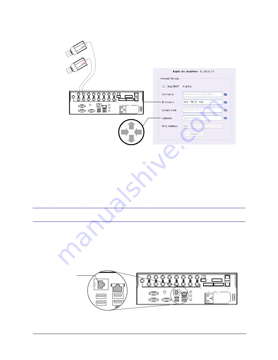
Figure 2-9
LocalView Panel for Network Settings
Testing a Network Connection in the Field
To test a network connection, PING the DVR.
Dial-up Connection
The internal modem is only supplied with North American Rapid Eye LT units. European
units requiring modem functionality require an external modem connected to Serial Port 1
or 2 (see the documentation that came with the external modem for connection
information). The following instructions describe using the internal modem with North
American units.
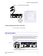
Figure 2-10
TELCO Port for Dial-up Connection (North American Units Only)
1. Using a standard telephone cable with RJ11 connectors, plug one connector into the
TELCO port on the DVR (see
164.178.32.1
SERIAL PORT 2
SERIAL PORT 1
VGA
TELCO
USB
USB
LAN
IN
OUT
NOT
USED
1
2
3
4
5
6
7
8
SPOT
MONITOR
VIDEO
INPUTS
COMMON
SYS FAIL
SYS GOOD
F
AULT
RELAY
28V, 3A
MAX
1 G
G
G
G
2
3
4
CONTROL
OUTPUTS
SERIAL
PORT 3
SERIAL
PORT 4
1 G
G
G
G
2
3
4
5 G
G
G
G
6
7
8
ALARM
INPUTS
ON/OFF
POWER
115-230V~
50/60 Hz
5-3A
TELCO
USB
LAN
SERIAL PORT 2
SERIAL PORT 1
VGA
TELCO
USB
USB
LAN
IN
OUT
NOT
USED
1
2
3
4
5
6
7
8
SPOT
MONITOR
VIDEO
INPUTS
COMMON
SYS FAIL
SYS GOOD
F
A U LT
R ELAY
28V, 3A
M A X
1 G
G
G
G
2
3
4
CONTROL
OUTPUTS
SERIAL
PORT 3
SERIAL
PORT 4
1 G
G
G
G
2
3
4
5 G
G
G
G
6
7
8
ALARM
INPUTS
ON/OFF
POWER
115-230V~
50/60 Hz
5-3A
Telco port
Summary of Contents for Rapid Eye LT
Page 1: ...Document 800 07766V1 Rev A 02 11 Installation Guide Rapid Eye LT Digital Video Recorder ...
Page 2: ......
Page 3: ...Installation Guide ...
Page 14: ...14 Contents ...
Page 16: ...16 Figures ...
Page 18: ...18 Tables ...
Page 76: ...76 ...
Page 77: ......


