50
Site Hardware
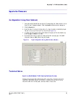
2. You have the option of rack-mounting the DVR. Leave at least a one-inch space on the
sides of the rack for ventilation.
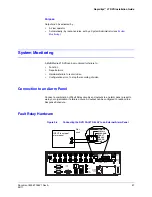
3. Plug the supplied power cord from the rear of the Multi-Media LT DVR to a grounded
power supply, preferably through an uninterruptible power supply (UPS).
Caution
Do not block the air intakes on the side of a Multi-Media LT DVR. A
warning sticker indicates this on the right-hand side of the DVR.
Do not place equipment, such as a monitor, directly on top of the
Multi-Media LT DVR.
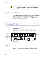
Connectors for Serial Communications
Ports 1 and 2
The wiring for the RS-232 connectors on a Multi-Media LT DVR’s Serial PORT 1 and PORT
2 is listed in
.
Figure 5-1
Pin Order on Ports 1 and 2 of a DB-9 Connector (View into the DVR)
Ports 3 and 4
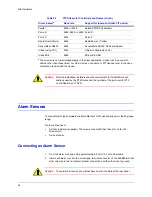
The wiring for the RJ45 connectors on a Multi-Media LT DVR’s Serial PORT 3 and PORT 4
is listed in
Table 5-1
Wiring an RS-232 Cable for Serial Use
RS-232 Pin-Out
1
DCD
6
DSR
2
RxD
7
RTS
3
TxD
8
CTS
4
DTR
9
RI
5
GND
Table 5-2
Wiring an RJ45 Cable for Serial Use
RS485 (half duplex)
GND - 4
+DX - 1
-DX - 2
Summary of Contents for Rapid Eye LT
Page 1: ...Document 800 07766V1 Rev A 02 11 Installation Guide Rapid Eye LT Digital Video Recorder ...
Page 2: ......
Page 3: ...Installation Guide ...
Page 14: ...14 Contents ...
Page 16: ...16 Figures ...
Page 18: ...18 Tables ...
Page 76: ...76 ...
Page 77: ......

