INSPECTION AND CLEANING
Occasionally, check for leaks and loose fittings and
screws. Especially check the self-tapping screw in Port 8
and the self-tapping screw at the top of the integral module
(RP920C and D).
NOTE: Once removed, self-tapping screws can be a
source of air leakage because of a damaged 0
ring. Check the O-ring and replace it if it is
damaged,
Use a soft cloth or brush to remove accumulated dust and/
or dirt from th e RP920.
OPERATIONAL CHECK
ALL SYSTEMS
Be certain all adjustment settings and conditions are
correct. See job drawing s
for
prope r
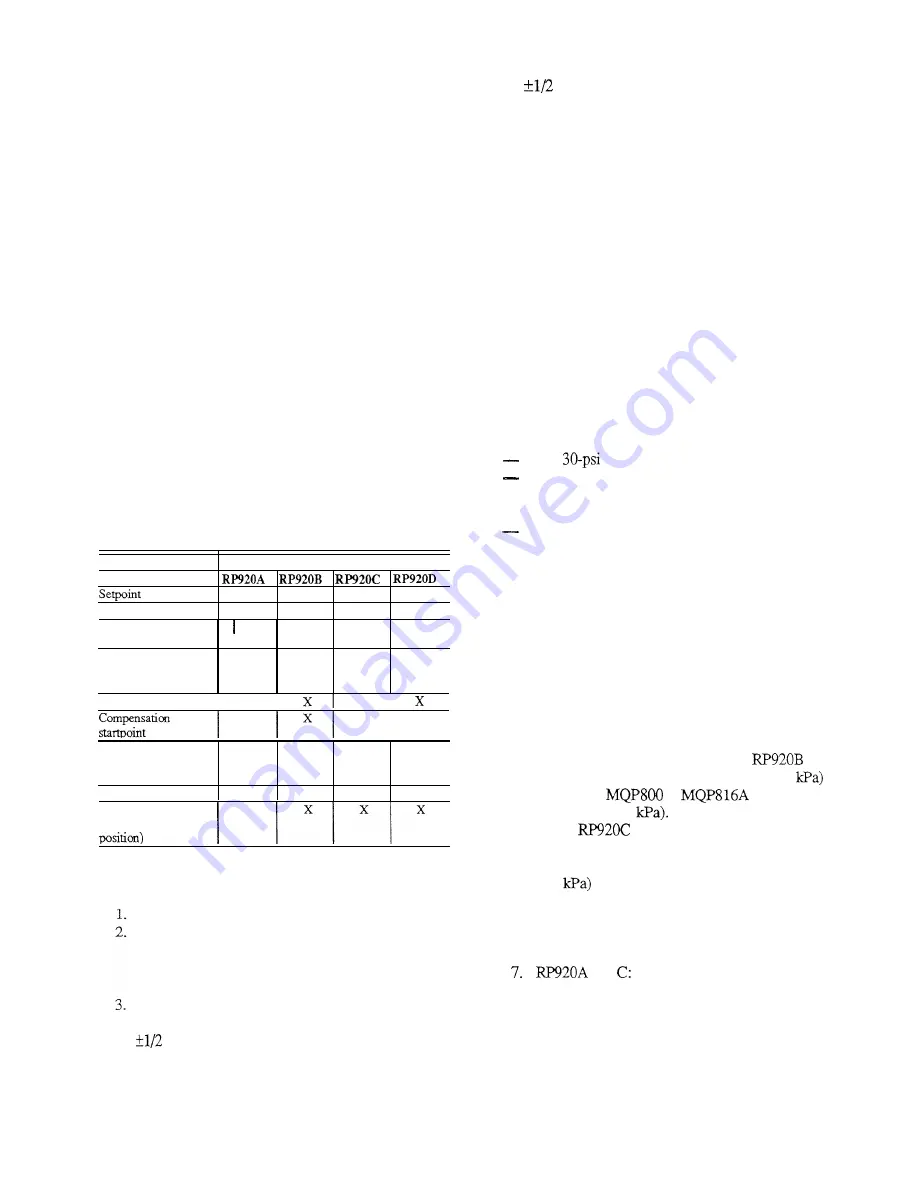
settings. Table 1 is a list
of the adjustments available on each model.
Table 1 . RP92 0 Adjustments.
of the throttling range as set by the authority and
compensation startpoint. If a discrepancy exists,
recalibrate the controller.
4.
Move th e setpoin t slightly up and down. The BLP
should change proportionally in the same direction
for direct acting and in the opposite direction for
reverse acting controllers. Repeat this step using the
CPA if applicable. If the BLP responds properly, the
controller is good. Return th e
setpoin t and CPA to the
original settings,
NOTE: The RP920C or D should maintai n
control
closer to th e setpoin t or reset schedule than
the RP920 A or B because of the integral
action.
SYSTEM NOT OPERATING-SENSORS
DISCONNECTED
EQUIPMENT
0- to
pressure gage.
Restricted air supply, adjustable from 3 to 15 psi (21
to 10 3 kPa) , with receiver gage to match sensors or
Sensor Controller Calibration Ki t
MQP816A.
Pneumatic Calibration Kit MQP80 0 (optional).
Model
Adjustment
X
X
X
X
Proportional Band
X
X
X
X
Internal restrictor
switch
X
I Xl
X I X
Direct/reverse acting
(proportional
module position)
X
X
X
X
PROCEDURE
1.
Connect the 0- t o30-psi gage to Port 2 (branch).
2.
Connect the main air supply to Port 1 (18 psi
minimum).
kPa ) adjustable air
3
supply with a receiver gage which matches the
I
I
I
3.
Pipe a 3 to 15 psi (21 to 10
Authority
primary sensor to Port 3.
X
4.
3
kPa ) adjustable
air supply with a receiver gage which matches the
compensation sensor to Port 5 of an
or D.
5.
If checking a CPA model, pipe 9 psi to (62
to
Port 9. The
or
can be used to
Pipe a second 3 to 15 psi (21 to 10
Positive/negative
compensation (switch
block module position
X
X
Reset time
X
X
Gage/integral cut-off
supply 9 psi (62
(switch block gasket
6.
On an
and D, remove and save the seal
screw from the integral module (Fig. 12) and install
Barb Fitting 14003755-001 in its place. Apply 8 psi
SYSTEM IN OPERATION
(55
to the integral module. This prevents
integral action. Without this procedure, it is
Be certain th eHVAC equipment is functional.
necessary to allow additional time for the controller
Observe BLP. If it is not between 3 and 13 psi (21 to
to finish responding to any change in input pressure
90 kPa) , slowly adjust th e setpoin t knob and/or CPA
or settings.
0
kPa ) range.
until the BLP is in the 3 to 13 psi (21 to 9
and
Allow the system to stabilize before continuing.
a .
Adjust the input air pressure to Por
3
t t o
Measure the temperature, humidity, or static pressure
correspond with the mid-point of the throttling
at the main sensor. This should agree with th
e
setpoint
range of the primary sensor (see APPENDIX
of the
throttling range .
For theRP920B and Dthe
A).
measurement should agree with the reset schedule
5
85-O 142


