EN2R-9031 0402R15-NE
52
SYSTEM OPERATION
S4575A, B, P, Q
General
The S4575A, B, D, P ignition controls can provide hot surface
ignition.
The
H
ot
S
urface
I
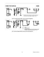
gniter (HSI is connected to a floating
winding of a transformer (see figFig. 65.).
Lock-out reset
The ignition control can be is reset by either depressing the
internal/external reset button (suffix A and B) or by
interrupting the permanent life (suffix P and Q).
NOTE 20.: If during normal use the reset button is pressed,
the gas valves close and the ignition control
starts a new sequence after releasing the reset
button.
NOTE 21.: If permanent alarm output: neon indicator with
integral resistor >150 k
Ω (
max 1 mA)
Do not connect any electrical load to the heat
demand input, it will influence proper functional-
ity.
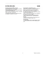
Suffix A and P (see Fig. 67.)
When there is a call for heat the HSI starts glowing during
glowing time (T
g
).
After the glowing time (T
g
) the gas valve is switched on.
The igniter ignites gas and resulting flame is detected by the
flame rod.
After flame establishment a predetermined, extended ignition
time can be included.
If flame is not established within the safety time (T
s
), the
ignition control locks out.
If the flame is lost during normal run, the ignition control
repeats start sequence.
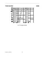
Suffix B and Q (see Fig. 68.)
As suffix A and P except flame relay contact is closed after
flame detection.
Gas/air application
For gas/air application without dynamic aircheck, the
S4565AD, BD, PD or QD can be used.
In this application the fan is connected between pin 4 and 5
and will start when a call for heat is present. The waiting
period now acts as a prepurge time.
When the call for heat disappears or when the ignition control
goes in lock-out, the fan will be switched off.


