S8700B,D-F,J-M DIRECT SPARK IGNITION CONTROLS
69-1299
8
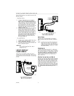
Check the flame sensing current from the sensor to the
S8700 as follows:
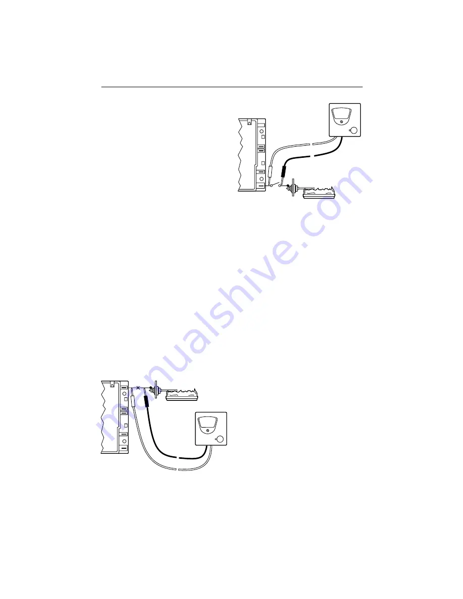
For S8700D,F,K,M:
1.
Connect an analog meter (dc microammeter
scale) in series with the flame sense lead as
shown in Fig. 6. Use the Honeywell W136A test
meter or equivalent. Disconnect the flame sense
wire from the sense terminal on the control. Con-
nect the red (positive) meter lead to the flame
sense terminal on the control. Connect the black
(negative) meter lead to the flame sense wire
leading to the flame rod.
2.
Restart the system and read the meter. The flame
sense current should be at least 2.0
µ
A and
steady to assure reliable appliance operation. If
the reading is less than 2.0
µ
A or unsteady, See
the Low Or Unsteady Flame Current section. If
flame is present at the sensor and a reading of
0
µ
A is obtained, check for damaged insulation or
ground path in the flame sensor wiring. Also
check for damaged, wet or dirty ceramic in the
flame sensor assembly.
For the S8700B,E,J,L:
1.
Connect a switch between the S8700 spark termi-
nal and the spark cable. See fig. 7.
2.
Attach meter leads on each side of the switch .
3.
Light burner with the switch closed, then open the
switch to read flame current.
IMPORTANT
Do not let spark energy enter the meter or
damage can result.
LOW OR UNSTEADY
FLAME CURRENT
If the current to the S8700 is less than 2.0
µ
A or is
unsteady, check the burner flame, flame sensor location
and electrical connections as described in the following
sections.
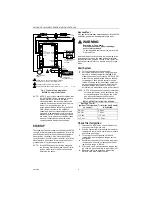
Fig. 6. S8700D,F,K,M dual-rod
flame current measurement.
Fig. 7. S7800B,E,J,L single rod
flame current measurement.
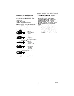
Burner Flame
The flame sensor must be constantly immersed in
flame. Check the burner flame conditions as shown in
Fig. 7.
NOTE:
Note:If the main burner flame is fluctuating or
lifting off the main burner, intermittent flame
signals can be generated. Adjust the appliance
so that the main flame is steady and not lifted
from the main burner.
Flame Sensor
The flame signal is best when about 1 in. (25 mm) of
flame rod is immersed in the burner flame. A bent flame
rod, bent mounting bracket or cracked ceramic insulator
can affect flame signal. A cracked ceramic insulator
may perform properly when cold, but can cause inter-
mittent operation when it heats up. Replace flame
sensor if necessary.
Electrical Connections and Shorts
All wiring must be in good condition; replace if insulation
shows any sign of damage. Connections at the S8700
and the flame sensor must be clean and tight. Wiring
between the main burner and the S8700 GND (burner)
terminal must also be in good condition. A jumper
between the GND (burner) terminal and the main burner
will often confirm if the flame circuit wiring needs atten-
tion. If wiring needs replacement, use moisture resistant
No. 18 wire rated for continuous duty up to 221
°
F
(105
°
C).
ALARM
VALVE
(GND)
SPARK
SENSE
RED (+)
BLACK (–)
ANALOG METER
DC MICROAMP
SCALE (MUST READ
TO 0.1 uA dc)
2.0
µ
A dc MINIMUM (AND STEADY)
M16236B
FLAME
SENSOR
BURNER
ALARM
VALVE
(GND)
SPARK
RED (+)
BLACK (–)
2.0
µ
A dc MINIMUM (AND STEADY)
M16664
FLAME
SENSOR
BURNER
SWITCH
ANALOG METER
DC MICROAMP
SCALE (MUST READ
TO 0.1 uA dc)
Summary of Contents for S8700 Series
Page 11: ...11 69 1299 ...


