background image

S9200U1000 UNIVERSAL HOT SURFACE IGNITION INTEGRATED FURNACE CONTROL

7

69-2075EF—01

Fig. 1. S9200U1000 dimensions in inches and (mm).

Wiring

WARNING

Fire or Explosion Hazard.
Can cause severe injury, property damage, or 
death.

Make sure the proper wiring harness is used. 
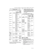
Check the cross reference tables (Table 1 on 
page 3)
 and review the appliance wiring 
schematic.

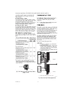
The S9200U1000 is intended to connect to the appliance 
with the aid of wiring harnesses. Carefully review the 
wiring harness selection table for the correct wiring 
harnesses. See Table 1 on page 3. 

Check the wiring diagram (Fig. 4 on page 9) and the 
diagram furnished by the appliance manufacturer for all 
terminal designations. Table 5 and Table 6 beginning on 
page 8 describe the wiring connections for Class 2 and 
Class 1 installations.

Typical wiring connections are shown in Fig. 5 on 
page 10.

Check the wiring diagrams furnished by the appliance 
manufacturer, if available, for circuits that differ from the 
general hookup shown. Carefully follow any special 
instructions affecting the general procedures outlined 
below.

All wiring must comply with local codes and ordinances. 

See “Wiring Harnesses”  for the main and igniter/inducer 
harness plug connections and details.

See “Wiring Connections” on page 8 for wiring 
connections, but also refer to furnace manufacturer 
instructions, if available.

NOTE: The Safety Timing jumper is described in Table 7 

on page 11.

IMPORTANT

The common ground required for the 

S9200U1000

 and the main burner must be sup-

plied through the plug connected to the Main 
Harness (12-pin connector) receptacle on the 
board.

Wiring Harnesses

The following describes the main and igniter/inducer 
harness connections.

MAIN HARNESS PLUG CONNECTIONS

The following describes the harness plug connectors for 
the main harness. See Table 3 and Fig. 2.

IMPORTANT

The common ground required for the 
S9200U1000 and the main burner must be sup-
plied through the plug connected to the Main 
Harness (12-pin connector) receptacle on the 
board. 

.

Fig. 2. S9200U1000 Main harness plug configuration.

4 1/8
(105)

1 1/2

(38)

6 1/8
(156)

M24905

Table 3. Main Harness Plug Connector 12-pin 

(Class 2, Low Voltage).

Pin #

Function

1

High  Limit  Out

2

Flame Sense - Flame Signal Input (90 Vac, current limited)

3

24  Vac  Hot

4

Not Used

5

Rollout Switch Out

6

24  Vac  Common

7

High Limit In + Pressure Switch Out

8

Chassis Ground

9

Main Valve Common

10

Pressure Switch In

11

Rollout Switch In

12

Main Valve

1                      4                      7                    10

2                      5                      8                       11

3                      6                      9                    12

M24906

Summary of Contents for S9200U1000

Page 1: ...emote system status diagnostics troubleshooting and HVAC system control SPECIFICATIONS Line Voltage Line 120V 97 132 Vac 60 Hz Low Voltage Line 24V 19 30 Vac 60 Hz Current Draw 0 5A Input Current 24 Vac plus valve load 24 Vac plus cooling contactor Igniter Current 5 0A resistive 132 Vac output Thermostat Anticipator Setting Stage 1 only 100mA Prepurge 30 seconds HSI Warm up 17 27 or 30 30 seconds ...

Page 2: ...fully identify and mark any wiring See Replacement on page 6 3 Mount the S9200U1000 Integrated Furnace Con trol See Replacement on page 6 4 Connect the wiring harnesses and make the wiring connections See Wiring on page 7 5 Configure the field settings and safety timings See Safety Timings Field Settings and Fixed Parame ters beginning on page 11 CROSS REFERENCE IMPORTANT Only use the S9200U1000 o...

Page 3: ...equired A Inducer HSI Connector SW1 ON SW2 OFF SW3 SW4 60 90 120 180 SW1 OFF SW2 ON 6DT 1 6DT 2 61F3 York 03100662000 031 00662 000 031 00662 700 031 01140 000 031 01140 001 031011140002 031 01140 002 031 01140 701 031 01140 702 031 01234 000 031 01234 700 031 01235 000 031 01235 700 031 01250 000 031 01266 000 031 01267 00 031 01267 000 031 01267 001 031 01267 001A 031 01284 000 031 01933 000 031...

Page 4: ...Universal A Inducer HSI Connector SW1 Check Settings SW2 Check Settings SW3 SW4 60 90 120 180 SW1 OFF SW2 OFF 50A55 286 SW1 ON SW2 OFF SW3 SW4 60 90 120 180 SW1 OFF SW2 ON 50A50 143 SW1 ON SW2 Check Settings SW3 SW4 60 90 120 180 SW1 OFF SW2 ON 50A55 241 SW1 ON SW2 OFF SW3 ON SW4 ON SW1 OFF SW2 ON 50A50 286 SW1 ON SW2 OFF SW3 SW4 60 90 120 180 SW1 OFF SW2 ON 50A50 438 SW1 Check Settings SW2 ON SW3...

Page 5: ...FF SW2 OFF 50A55 288 A Inducer HSI Connector SW1 ON SW2 OFF SW3 SW4 60 90 120 180 50A50 285 SW1 OFF SW2 OFF SW3 ON SW4 OFF 50A55 285 G SW1 ON SW2 OFF SW3 SW4 60 90 120 180 Amana1 10207701 A Inducer HSI Connector SW1 ON SW2 OFF SW3 ON SW4 OFF SW1 OFF SW2 ON 10207702 10207703 10207710 ICP 1010806 A Inducer HSI Connector SW1 ON SW2 OFF SW3 SW4 60 90 120 180 SW1 OFF SW2 OFF 1380 686 SW1 OFF SW2 ON 138...

Page 6: ...control and identify mark all wires not connected to a wiring plug 3 Once the furnace control is free from all wiring either unclip or unscrew the furnace control from the base plate 4 Select the location within the appliance most suit able so that all existing cables or required har nesses will reach without straining either the cables or the plugs We recommend mounting the S9200U1000 in the same...

Page 7: ...nces See Wiring Harnesses for the main and igniter inducer harness plug connections and details See Wiring Connections on page 8 for wiring connections but also refer to furnace manufacturer instructions if available NOTE The Safety Timing jumper is described in Table 7 on page 11 IMPORTANT The common ground required for the S9200U1000 and the main burner must be sup plied through the plug connect...

Page 8: ...g contactor output for EnviraCOM thermostats 4 3 2 1 M24907 Polarized3 pin connector E COM EnviraCOM diagnostic or communications device 12 pin connector Main Harness Connector See Table 3 on page 7 StraightSpade Quick connect 24 Vac Transformer 24 Vac COM Transformer Common Fuse Block Fuse Fuse Automotive Type 3 0 Amps Table 6 Wiring Connections Class 1 Line Voltage Terminal Type Connection see F...

Page 9: ...ing wiring connections and components of the S9200U1000 Universal Integrated Furnace Control E COM LOCKOUT JUMPER FLAME STATUS E COM FUSE XFMR 24 VAC COM FLAME HEAT EAC COOL NEUTRALS PARK PARK HUM D 1 C 3 R 2 W G Y ON ON S1 S2 1 2 3 4 1 2 ON CONT MOUNTING HOLE X2 BOARD CLIPS X6 PLASTIC MOUNTING TRAY M24908A L1 1 4 10 7 4 1 ...

Page 10: ... 2 W G Y ON CONT M24916A L1 1 4 10 7 4 1 IGNITER INDUCER MOTOR HUMIDIFIER CIRCULATOR BLOWER ELECTRONIC AIR CLEANER EnviraCOM THERMOSTAT 1 2 3 CONVENTIONAL THERMOSTAT W G Y R C W NEUTRAL L1 24 VAC 120 VAC 120 VAC 1 SEE TABLE 2 AND FIGURE 2 FOR MAIN HARNESS PLUG CONNECTIONS SEE TABLE 3 AND FIGURE 3 FOR IGNITER INDUCER HARNESS CONNECTIONS 1 2 2 FLAME SENSE GND HIGH LIMIT SWITCH MAIN VALVE ROLLOUT SWI...

Page 11: ...r installation See DIP Switch S1 Field Settings on this page Fixed Parameters Fixed parameters are those settings which may not be adjusted at any time Table 8 describes the S9200U1000 Fixed parameters DIP Switch S1 and S2 settings The following field and safety parameters may be set using DIP switches S1 and S2 Refer to Fig 4 on page 9 for the location of the two DIP switch blocks DIP Switch S1 F...

Page 12: ...maining control reverts back to standard operation only after power to the control is cycled For twinning applications Honeywell recommends that DIP switch S1 be set to the same positions on each device so that the heat cool fan on off delay times are equal for both devices Otherwise the shorter Fan On delay and the longer Fan Off Delay times are used for both devices See Fig 8 for typical wiring ...

Page 13: ...the pressure switch cir cuit is open The S9200U1000 energizes the inducer After the Pressure Switch closes Prepurge begins After the completion of Prepurge the HSI is ener gized for the Igniter Warm up Period When the Igniter Warm up Period expires the gas valve is energized and the Trial for Ignition begins During the Ignition Activation Period both the HSI element and the gas valve remain energi...

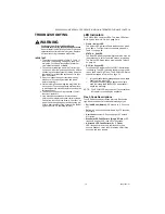
Page 14: ...e and sent on the bus see Table 14 on page 22 As soon as the pressure switch opens the error code clears and the ignition sequence proceeds as normal If the ignition sequence has begun and the pres sure switch fails to close within 150 seconds of energizing the inducer the S9200U1000 de ener gizes the inducer starts flashing the Pressure Switch Failed Open error code and returns to Idle Mode for f...

Page 15: ...e bus See Table 14 on page 22 If the inducer is energized or the pressure switch is closed and the inducer is not energized pressure switch is stuck closed and the main valve relay contacts are sensed closed even though the relay is not energized welded contacts An error code flashes indicating there is a hard ware malfunction See Table 12 on page 20 An EnviraCOM alarm is active and sent on the bu...

Page 16: ...are ignored The S9200U1000 flashes an error code indicating a bad fuse See Table 12 on page 20 An EnviraCOM alarm is active and sent on the bus See Table 14 on page 22 The alarm may not be received due to low line voltage but will be stored in the alarm history Once a good fuse is detected the S9200U1000 returns back to normal operation through a micro reset Soft Lockout Soft Lockout is intended t...

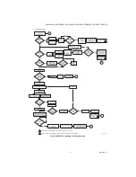
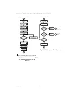
Page 17: ...ER STARTED INTERPURGE H S I OFF ROLLOUT CIRCUIT CLOSES NO INDUCER OFF AFTER POST PURGE INDUCER OFF AFTER POST PURGE CIRCULATOR OFF AFTER HEAT FAN OFF DELAY HEAT SPEED YES YES 1 1 M24911A LIMIT SWITCH CLOSED WITHIN 3 MINUTES 1 SOFT LOCKOUT AUTOMATICALLY RESETS AFTER ONE 1 HOUR 2 HARD LOCKOUT REQUIRES CYCLING OF POWER TO RESET THE LOCKOUT HARD LOCKOUT ERROR CODE FLASHES 2 PRESSURE SWITCH OPEN SOFT L...

Page 18: ...E DE ENERGIZE CIRCULATOR COOLING REQUEST STILL ACTIVE ENERGIZE AND MAINTAIN CIRCULATOR AT COOLING MODE YES M24912A 2 1 THE OPERATION IN THE BLOCK IS SKIPPED WHEN A SYSTEM WITH A CONVENTIONAL THERMOSTAT IS USED THE OPERATION IS PERFORMED IN SYSTEMS WITH AN ENVIRACOM THERMOSTAT ONLY 2 1 1 1 WAIT FOR COOL FAN OFF DELAY TO EXPIRE NO CALL FOR FAN 3 CALL FOR FAN CIRCULATOR ON HEAT SPEED REQUEST FOR COOL...

Page 19: ...ut the system again to be sure it is operating normally LED Indicators The S9200U1000 has three LEDs The three LEDs from left to right as shown in Fig 4 on page 9 are Flame Amber LED The Amber LED Indicates flame status such as weak or no flame The Flame status codes are mapped in Table 11 on page 20 STATUS Red LED The Red LED indicates general system status such as the presence of a call for heat...

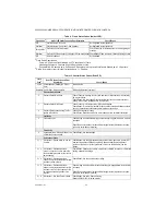
Page 20: ...ntacts closed when should be open pressure switch hoses have water build up or obstruction 4 Pressure Switch opened during Trial For Ignition or Run Mode Check See if inducer is running Check Repair Restricted venting low input voltage water in horizontal vent length Limit Code 5 Limit switch open Check Wiring restricted airflow through heat exchanger clogged filters slow circulator fan speed Repa...

Page 21: ...ne volt hot lead is not attached to the L1 input Hard Lockout Codes 4 1 Hard Lockout Rollout circuit open or previously opened Check Repair Flue restrictions heat exchanger restricted Check burner Check Rollout Switch including switch cables Reset rollout if necessary Do not operate until repairs are made Cycle power to appliance and run heating sequence If this failure repeats replace the control...

Page 22: ...ermostat screw terminal R 2 to D 1 jum pered After a 5 second time out the red status LED turns off After a 10 second time out the red status LED turns on solid to indicate that the error history is being cleared 3 When the error history is cleared the red status LED returns to normal operation 4 Remove the thermostat screw terminal R 2 to termi nal D 1 jumper EnviraCOM Communication EnviraCOM com...

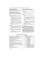
Page 23: ...s indicating the failure See Table 12 on page 20 An EnviraCOM alarm is active and sent on the bus See Table 14 on page 22 Test Mode is exited after any of the following conditions Three minutes of operation Receipt of an EnviraCOM command instructing the S9200U1000 to exit Test Mode The cycling of power Earth ground problem 88 Display Diagnostics EnviraLNK TAM A bad fuse has been detected NOTE Thi...

Page 24: ...den Valley MN 55422 Honeywell Limited Honeywell Limitée 35 Dynamic Drive Toronto Ontario M1V 4Z9 customer honeywell com U S Registered Trademark 2010 Honeywell International Inc 69 2075EF 01 M S 10 10 Printed in U S A QuickLook 72 is a trademark of OnWatch Electronics Inc EnviraCom is a trademark of Honeywell EnviraLNK is a registered trademark of Honeywell ...

Page 25: ...unication avec les appareils de diagnostic locaux et à distance tels que l appareil de poche QuickLook QuickLook 72 le module d application Web EnviraLNK et le modèle d accès téléphonique TAM W8735D CARACTÉRISTIQUES Caractéristiques du S9200U1000 Allumage du brûleur principal à l aide d un allumeur à incandescence de 120 V Circuit de redressement de flamme pour surveiller la présence de la flamme ...

Page 26: ...che air froid du ventilateur 5 s Délai d arrêt air froid du ventilateur 0 ou 60 s en fonction du réglage du commutateur DIP S1 Régulateur à gaz tout régulateur à gaz à allumage direct redondant de 24 V c a de 1 5 A ou moins Hon eywell Contacteur de refroidissement tout contacteur de 24 V c a de 1 0 A ou moins Ventilateur de tirage 2 2 A à pleine charge 3 5 A à rotor bloqué max à 120 V c a Charge d...

Page 27: ...t SW4 60 90 120 180 SW1 MARCHE SW2 ARRÊT 1012 955A 1012955A Texas Instruments Connecteur principal non requis A Connecteur de roue de tirage et HSI SW1 MARCHE SW2 ARRÊT SW3 et SW4 60 90 120 180 SW1 ARRÊT SW2 MARCHE 6DT 1 6DT 2 61F3 York 03100662000 031 00662 000 031 00662 700 031 01140 000 031 01140 001 031011140002 031 01140 002 031 01140 701 031 01140 702 031 01234 000 031 01234 700 031 01235 00...

Page 28: ...ité commutateur DIP S2 White Rodgers1 50A55 843 Universel A Connecteur de roue de tirage et HSI SW1 Vérifiez les réglages SW2 Vérifiez les réglages SW3 et SW4 60 90 120 180 SW1 ARRÊT SW2 ARRÊT 50A55 286 SW1 MARCHE SW2 ARRÊT SW3 et SW4 60 90 120 180 SW1 ARRÊT SW2 MARCHE 50A50 143 SW1 MARCHE SW2 Vérifiez les réglages SW3 et SW4 60 90 120 180 SW1 ARRÊT SW2 MARCHE 50A55 241 SW1 MARCHE SW2 ARRÊT SW3 MA...

Page 29: ...ÊT SW1 ARRÊT SW2 MARCHE 10207702 10207703 10207710 ICP 1010806 A Connecteur de roue de tirage et HSI SW1 MARCHE SW2 ARRÊT SW3 et SW4 60 90 120 180 SW1 ARRÊT SW2 ARRÊT 1380 686 SW1 ARRÊT SW2 MARCHE 1380 699 SW1 ARRÊT SW2 MARCHE Lennox 1214201 A Connecteur de roue de tirage et HSI SW1 MARCHE SW2 ARRÊT SW3 MARCHE SW4 ARRÊT SW1 ARRÊT SW2 ARRÊT Tableau 1 Le S9200U1000 remplace ces régulateurs d apparei...

Page 30: ... Températures de fonctionnement ambiantes entre 40 C 40 F et 79 C 175 F Humidité relative inférieure à 95 sans condensation Protection contre l eau la vapeur et les produits chimiques corrosifs utilisés pour nettoyer l appareil Protection contre l eau suintante telle que provenant d un humidificateur trop rempli ou de condensation Protection contre l accumulation de graisse ou de poussière IMPORTA...

Page 31: ...page 9 et le schéma fourni par le fabricant de l appareil pour connaître toutes les désignations de bornes Les tableaux 5 et 6 présentés à partir à la page 8 décrivent les connexions de câblage pour les installations de classes 2 et 1 Des connexions de câblage sont illustrées dans la fig 5 à la page 10 Consultez les schémas de câblage fournis par le fabricant de l appareil si disponibles pour conn...

Page 32: ...9200U1000 5 Interrupteur du système 6 24 V c a commun 7 Entrée haute limite sortie pressostat 8 Mise à la terre du bâti 9 Vanne principale commune 10 Entrée pressostat 11 Entrée interrupteur du système 12 Vanne principale Table 3 Connecteur à douze broches du faisceau de câblage principal classe 2 basse tension Broche no Fonction 1 4 7 10 2 5 8 11 3 6 9 12 M24906 ...
Page 33: ...rmostat refroidissement sortie du contacteur des thermostats EnviraCOM refroidissement Connecteur polarisé à trois broches E COM Dispositif de diagnostic et de communication EnviraCOM 4 3 2 1 M24907 Connecteur à 12 broches Connecteur de faisceau principal Voir le tableau 3 à la page 7 Cosse droite rapide 24 V c a Transformateur 24 V c a COM Transformateur commun Bloc de fusibles Fusible Fusible ty...

Page 34: ... connexions de câblage et les composants du régulateur d appareil de chauffage intégré S9200U1000 universel E COM LOCKOUT JUMPER FLAME STATUS E COM FUSE XFMR 24 VAC COM FLAME HEAT EAC COOL NEUTRAL PARK PARK HUM D 1 C 3 R 2 W G Y ON ON S1 S2 1 2 3 4 1 2 ON CONT TROU DE MONTAGE X2 ATTACHES POUR TABLEAU X6 PLATEAU DE MONTAGE EN PLASTIQUE MF24908A L1 1 4 10 7 4 1 ...

Page 35: ...DE ROUE DE TIRAGE HUMIDIFICATEUR SOUFFLANTE DE CIRCULATEUR FILTRE À AIR ÉLECTRONIQUE THERMOSTAT EnviraCOM 1 2 3 THERMOSTAT TRADITIONNEL W G Y R C W NEUTRE L1 24 V c a 120 V c a 120 V c a 1 CONSULTEZ LE TABLEAU 2 ET LA FIGURE 2 POUR LES CONNECTEURS DU FAISCEAU DE CÂBLAGE PRINCIPAL CONSULTEZ LE TABLEAU 3 ET LA FIGURE 3 POUR LES CONNEXIONS DE FAISCEAU DE CÂBLAGE DE L ALLUMEUR ROUE DE TIRAGE 1 2 2 DÉT...

Page 36: ...ges sur site Les réglages sur site peuvent être modifiés au besoin Le changement sera appliqué lors des prochaines situations influencées par ce changement Si par exemple un délai particulier s écoule et que les réglages sont modifiés le réglage de délai actuel n est pas influencé par ce changement Les réglages sur site ne sont pas considérés comme étant critiques pour la sécurité ces paramètres p...

Page 37: ...ommutateur DIP Switch S2 illustré avec les réglages d usine par défaut tous sur ARRÊT Table 9 Réglages du commutateur DIP S1 réglages sur site Descriptions du commutateur DIP S1 Commutateurs individuels SW1 SW2 SW3 SW4 Délai d arrêt air froid du ventilateur 0 seconde ARRÊT Délai d arrêt air froid du ventilateur 60 s MARCHE Délai de marche air chaud du ventilateur 30 s ARRÊT Délai de marche air cha...

Page 38: ...commande de placer le commutateur DIP S1 aux mêmes positions sur chaque appareil de manière à ce que les délais de temporisation air chaud marche air froid du ventilateur arrêt soient les mêmes pour les deux dispositifs Autrement des délais de temporisation marche plus court et arrêt ventilateur plus long seront utilisés pour les deux dispositifs Voir la fig 8 pour connaître les connexions de câbl...

Page 39: ...borne Y Lors d un appel de chaleur Le S9200U1000 effectue une vérification de sécu rité qui consiste en un autodiagnostic du matériel interne des logiciels et une vérification de l absence de flamme au brûleur principal Le S9200U1000 s assure que les circuits de l interrupteur du système et du limiteur sont fer més Le S9200U1000 s assure que le circuit du pres sostat est ouvert Le S9200U1000 met l...

Page 40: ...ur s ouvre durant le fonctionnement la séquence est considérée comme infructueuse le prochain essai est remis en cycle Le S9200U1000 demeure dans cet état jusqu à ce que le circuit du limiteur se ferme Après la fermeture du circuit du limiteur Si le circuit du limiteur était ouvert pendant moins de trois minutes une nouvelle séquence d allum age démarre et le circulateur reste sous tension pendant...

Page 41: ... en même temps que la roue de tirage Filtre à air électronique La sortie tension secteur de l EAC se met sous tension en même temps que le circulateur II VÉRIFICATION DE LA COUPURE DE SÉCURITÉ 1 Coupez l alimentation en gaz au niveau du robinet de gaz manuel de l appareil 2 Réglez le thermostat sur Appel de chaleur Le système doit fonctionner comme l indique la fig 9 à la page 17 3 Après le verrou...

Page 42: ...u niveau de la vanne pendant une période plus longue que celle correspondant à la durée de la défaillance de l antirebond alors que la vanne doit être mise sous tension les contacts ne se sont pas établis le S9200U1000 procède comme si la flamme n est pas détectée Si le verrouillage de premier niveau est activé en raison de cette situation Un code d erreur clignote indiquant un dysfonctionnement d...

Page 43: ... mais sera conservée dans l historique des alarmes Lorsque la tension se rétablit le S9200U1000 se remet à fonctionner normalement cinq s après la suppression de la défaillance Fusible défaillant Si un fusible défaillant est détecté le S9200U1000 se comporte de la manière suivante Les demandes de thermostat qui sont en cours deviennent inactives et sont interrompues comme si elles avaient été annu...

Page 44: ...chaleur du thermostat sont ignorées Les demandes de refroidissement du thermostat sont traitées normalement Les demandes de ventilation sont traitées nor malement Le S9200U1000 affiche un code de panne par intermittence identifiant la défaillance qui a causé la transition vers le verrouillage autocontrôlé Voir le tableau 12 à la page 20 Une alarme EnviraCOM indiquant que la défail lance est activé...

Page 45: ...APRÈS LE POSTBALAYAGE ROUE DE TIRAGE HORS FONCTION APRÈS LE POSTBALAYAGE CIRCULATEUR HORS FONCTION APRÈS LE DÉLAI D ARRÊT AIR CHAUD DU VENTILATEUR VITESSE DE CHAUFFAGE OUI OUI 1 1 MF24911A LIMITEUR FERMÉ EN 3 MINUTES 1 LE VERROUILLAGE DE PREMIER NIVEAU SE RÉINITIALISE AUTOMATIQUEMENT APRÈS UNE 1 HEURE 2 UN VERROUILLAGE DE DEUXIÈME NIVEAU REQUIERT LA MISE EN CYCLE DE L ALIMENTATION POUR RÉINITIALIS...

Page 46: ...IRCULATEUR HORS TENSION LA DEMANDE DE REFROIDISSEMENT EST ELLE ENCORE ACTIVÉE METTEZ LE CIRCULATEUR SOUS TENSION EN MODE DE REFROIDISSEMENT OUI MF24912A 2 1 LE FONCTIONNEMENT DANS LE BLOC EST OMIS SI UN SYSTÈME MUNI D UN THERMOSTAT TRADITIONNEL EST UTILISÉ L APPLICATION FONCTIONNE UNIQUEMENT DANS LES SYSTÈMES DOTÉS D UN THERMOSTAT ENVIRACOM 2 1 1 1 ATTENDEZ QUE LE DÉLAI DE MARCHE AIR FROID DU VENT...

Page 47: ...nt placés de gauche à droite comme le montre la fig 4 à la page 9 Flamme voyant DEL ambre Le voyant DEL indique l état de la flamme comme une flamme faible ou une absence de flamme Les codes d état de la flamme sont mis en correspondance le tableau 11 à la page 20 ÉTAT voyant DEL rouge Le voyant rouge DEL indique l état général du système comme la présence d un appel de chaleur et de codes d erreu...

Page 48: ...ranchés ou le relais de roue de tirage K4 pourrait être défaillant Vérifiez réparez basse tension câblage du pressostat desserré tuyau débranché ou qui fuit eau dans le tuyau ventilation bloquée ou obstruée 3 Le pressostat ne s est pas fermé Vérifiez si la roue de tirage est arrêtée le relais de roue de tirage K4 devrait être soudé Vérifiez réparez Bornes de câblage court circuitées contacts du pr...

Page 49: ...lage de la vanne à gaz Remettez les appareils sous tension Exécutez ensuite la séquence de chauffage 3 5 Échec de la procédure d autovérification du régulateur erreur interne ou matériel défaillant le régulateur redémarre si l erreur est corrigée Cela couvre les erreurs relatives au matériel comme les défaillances du circuit du détecteur de flamme les courts circuits de broches etc Remettez les ap...

Page 50: ...ncé clignotement X Y le voyant DEL clignote X fois à 2 Hz s éteint pendant une seconde clignote Y fois à 2 Hz reste éteint pendant trois s puis répète la séquence Table 13 Codes d état E COM voyant DEL vert Code de clignotement Code d état du voyant DEL vert et description a a Ce voyant DEL est activé même si un thermostat traditionnel régule l appareil Vérifiez réparez Clignotement rapide Activit...

Page 51: ...i de 0 5 seconde le voyant d état DEL rouge cesse de fonctionner normalement et reste allumé pour indiquer la détection du cavalier 2 Gardez le cavalier reliant la borne à vis R 2 du ther mostat à l entrée D 1 en place Après une pause de 5 s le voyant d état DEL rouge s éteint Après une pause de 10 s le voyant d état DEL rouge s éteint indiquant la suppression de l historique des erreurs 3 Une foi...

Page 52: ...ption d une commande EnviraCOM exigeant au mode d essai de quitter le S9200U1000 La mise en cycle de l alimentation La vanne à gaz n a pas réussi à se mettre sous tension 17 Affichage diagnostics EnviraLNK TAM Les composants électroniques ne fonctionnent plus 18 Affichage diagnostics EnviraLNK TAM Polarité de ligne inversée 33 Affichage diagnostics EnviraLNK TAM Une réinitialisation manuelle est r...

Page 53: ...RÉGULATEUR D APPAREIL DE CHAUFFAGE INTÉGRÉ À ALLUMAGE PAR INCANDESCENCE UNIVERSEL S9200U1000 29 69 2075EF 01 ...

Page 54: ...RÉGULATEUR D APPAREIL DE CHAUFFAGE INTÉGRÉ À ALLUMAGE PAR INCANDESCENCE UNIVERSEL S9200U1000 69 2075EF 01 30 ...

Page 55: ...RÉGULATEUR D APPAREIL DE CHAUFFAGE INTÉGRÉ À ALLUMAGE PAR INCANDESCENCE UNIVERSEL S9200U1000 31 69 2075EF 01 ...

Page 56: ...22 Honeywell Limited Honeywell Limitée 35 Dynamic Drive Toronto Ontario M1V 4Z9 customer honeywell com Marque de commerce déposée aux É U 2010 Honeywell International Inc Tous droits réservés 69 2075EF 01 M S 10 10 Imprimé aux États Unis QuickLook 72 est une marque de commerce de OnWatch Electronics Inc EnviraCom est une marque de commerce de Honeywell EnviraLNK est une marque déposée de Honeywell...

Reviews: