S9240F2051 MODULATING INTEGRATED FURNACE CONTROL
69-2807—01
10
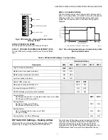
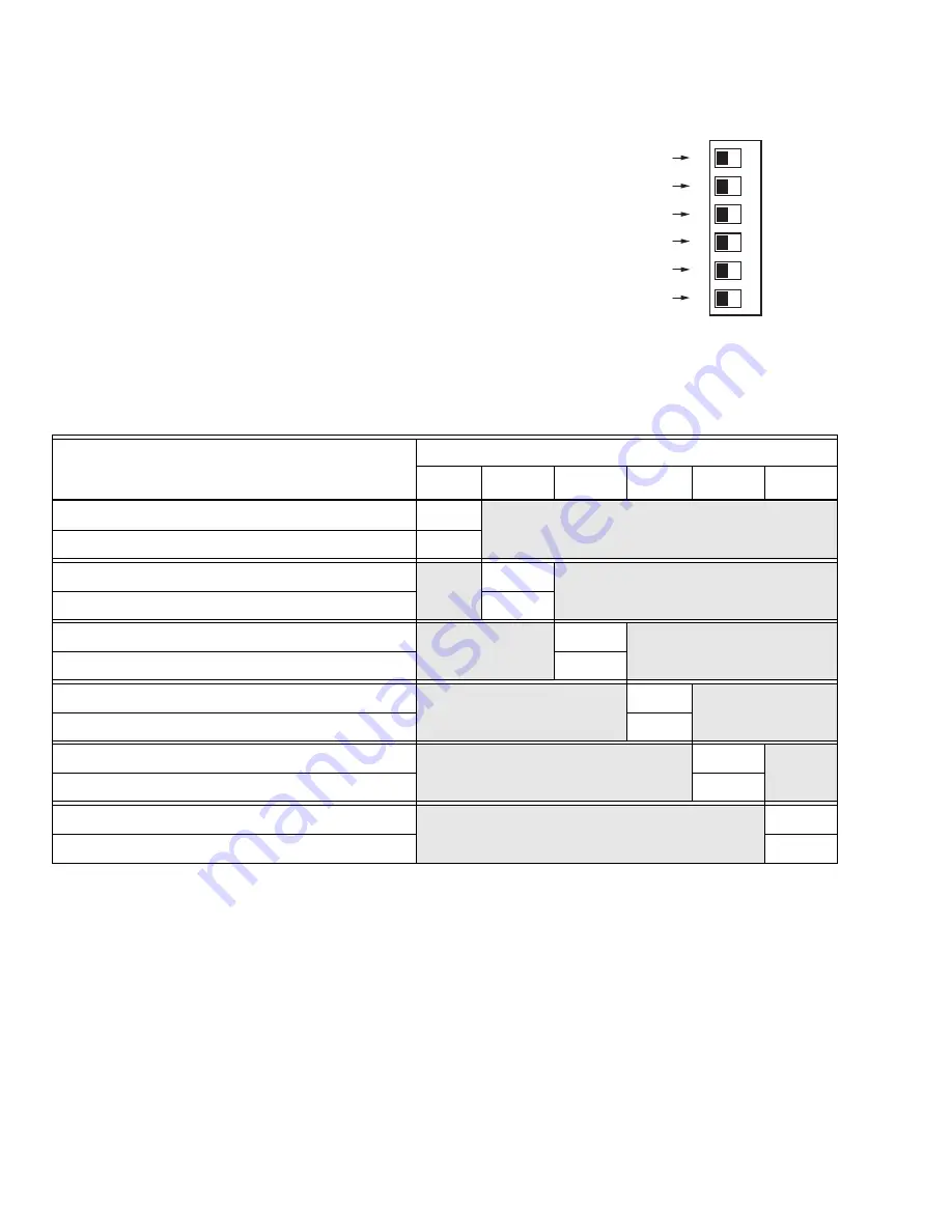
The default factory settings (all OFF) are shown in Fig. 8 and
indicated in Bold in Table 7.
To change any setting, first disconnect the power, then set
SW14
through
SW19
according to Table 7.
.
Fig. 8. DIP Switch S3 - shown with factory
default settings; all OFF.
.
DIP SWITCH S3
M28153
14
15
17
16
18
19
LOW HEAT CFM CHANGE (7% OR 15%)
LOW HEAT CFM (NORMAL/MODIFIED)
LOW HEAT CFM (INCREASE/DECREASE)
HIGH HEAT CFM CHANGE (7% OR 15%)
HIGH HEAT CFM (NORMAL/MODIFIED)
HIGH HEAT CFM (INCREASE/DECREASE)
ON
Table 7. DIP Switch S3 Settings – Heating Airflow.
Description
Individual Switches
SW14
SW15
a
a
Switch 15 is ignored if switch 14 is in the OFF position.
SW16
b
b
Switch 16 is ignored if switch 14 is in the OFF position.
SW17
SW18
c
c
Switch 18 is ignored if switch 17 is in the OFF position.
SW19
d
d
Switch 19 is ignored if switch 17 is in the OFF position.
Normal Low Heat CFM
OFF
Modified Low Heat CFM
ON
Increase Low Heat CFM
OFF
Decrease Low Heat CFM
ON
Change Low Heat CFM by 7%
OFF
Change Low Heat CFM by 15%
ON
Normal High Heat CFM
OFF
Modified High Heat CFM
ON
Increase High Heat CFM
OFF
Decrease High Heat CFM
ON
Change High Heat CFM by 7%
OFF
Change High Heat CFM by 15%
ON

