background image

S9240F2051 MODULATING INTEGRATED FURNACE CONTROL

69-2807—01

22

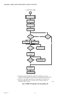
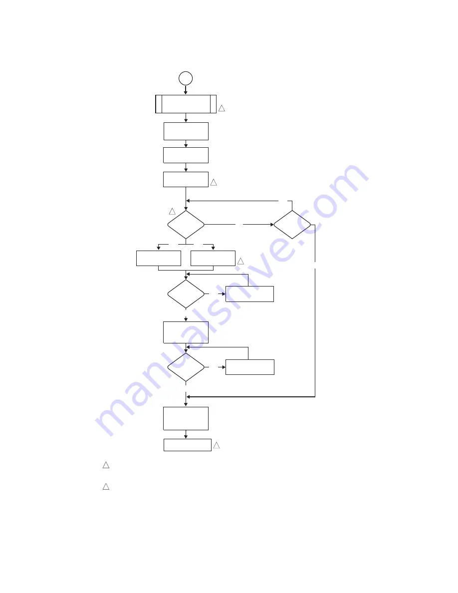
Fig. 13. S9240F IFC sequence Cooling Mode cycle.

1st Stage Cooling

Request Received

5. Call for Cooling

Energize 1st Stage

Cooling Contactor

(Compressor & Fan)

Energize Circulator

(Per Ramping Profile)

Circulator ON After

2 Second Delay

2nd Stage

Cooling

Request?

YES

2nd Stage

Cooling Request

Still Active?

De-Energize 1st

Stage Cooling

Contactor

(Compressor & Fan)

YES

1st Stage

Cooling Request

Still Active?

NO

YES

YES

Energize 2nd Stage

Cooling Contactor

(Compressor & Fan)

1st Stage

Cooling Request

Still Active?

De-Energize 2nd

Stage Cooling

Contactor

(Compressor & Fan)

Energize and

Maintain Circulator at

Low Cooling mode

Energize Circulator

(High Cooling mode)

Maintain Circulator

(High Cooling mode)

M28158

De-energize Circulator

Per Ramping Profile

NO

NO

YES

NO

5

2ND STAGE COOLING OPERATION REQUIRES A 2-STAGE THERMOSTAT, A 2-STAGE
COOLING SYSTEM, AND JUMPER W915 MUST BE CUT. THE CONTROL WILL NOT RESPOND TO 
A 2ND STAGE COOLING REQUEST UNLESS A 1ST STAGE COOLING REQUEST IS ACTIVE.

CIRCULATOR LOW COOLING MODE AND HIGH COOLING MODE HAVE SPECIFIC ON, OFF, 
AND SPEED RAMPING PROFILES. THE SPECIFIC PROFILE IS SELECTED USING THE
DIP SWITCHES ON THE CONTROL.

1

2

1

2

2

2

1

Summary of Contents for S9240F2051

Page 1: ...a main burner flame up to 400 000 BTU per hour using a 120 Vac hot surface igniter Monitors the appliance pressure limit and rollout switches and generate control actions as programmed Controls the 24 Vac Honeywell amplified gas air gas valve Controls a 3 phase 120 Vac inducer motor Fasco Model 92B1 or other with identical voltage frequency curve and blower assembly based on heat demand and other ...

Page 2: ...cognition Delay 30 seconds only on First Call for High Fire on a Call for Heat Second Stage ON Delay 7 or 12 minutes when used with a single stage thermostat see Table 5 on page 8 default is 7 minutes Third Stage ON Delay 10 minutes when used with a single stage thermostat Fan Delays Heat Fan ON Delay 30 seconds Heat Fan OFF Delay 60 90 120 or 180 seconds default 90 seconds see Table 5 on page 8 C...

Page 3: ...er or from condensation Protection from dust or grease accumulation Mounting The integrated furnace control is designed to snap into the appliance mounting panel 1 While holding the controller board with the thermostat terminals E7 at the bottom insert the two left side hooks on the board into the holes in the mounting panel See Fig 1 on page 5 2 Press the board into the mounting panel s right sid...

Page 4: ...rnace size select input Table 2 Wiring Connections Class 1 Line Voltage Continued Terminal Type Connection Label Board label see Fig 1 Connects S9240F to 2 pin connector male terminals Igniter P77 HSI Igniter interface 3 pin connector male terminals CAI Connector J3 CAI 3 phase AC power Straight Spade Quick connect Humidifier HUM Humidifier 120 Vac output EAC EAC Electronic air cleaner 120 Vac out...

Page 5: ... STAGE COMPR CUT FOR OPTION SELECTION W1 W2 G Y2 Y1 DH H O DS C OUTDOOR EQUIPMENT INDOOR EQUIPMENT R C I I L R I TEMPERATURE SENSORS E4 LED E7 L1 P79 CIRCULATOR MOTOR HARNESS J2 MAIN HARNESS NEUTRALS E36 E37 E38 E39 AND E40 HUM EAC W914 DEHUM JUMPER W951 HEAT PUMP JUMPER W915 2 STAGE COMPR JUMPER HSI P79 ON ON ON FACTORY USE ONLY OUTDOOR AIR SENSOR USED ONLY IN A COMMUNICATING SYSTEM THIS SENSOR I...

Page 6: ... LINE VOLTAGE HUMIDIFIER OPTIONAL ELECTRONIC AIR CLEANER OPTIONAL ECM INDOOR AIR BLOWER 24 VAC MAIN VALVE LOW PRESSURE SWITCH HIGH LIMIT SWITCH ROLLOUT SWITCH HIGH PRESSURE SWITCH W951 W914 W915 24V HUMIDIFIER OPTIONAL L1 NEUTRAL 1 2 P77 HSI P79 J3 CAI J2 E7 E4 M W1 G Y2 Y1 C R DH H L O DS W2 FURNACE SIZE IDENTIFIER L2 L1 M 2 1 OUTDOOR AIR SENSOR OPTIONAL E4 AUXILIARY CONNECTOR OPTIONAL E33 I I CO...

Page 7: ...st disconnect the power then set SW1 through SW7 according to Table 5 on page 8 Fig 5 DIP Switch S1 shown with factory default settings all OFF SW1 STAGE SELECTION The stage selection is factory set OFF to a 2 stage thermostat with the 2nd and 3rd stage On Delays disabled The ON position configures the IFC for a single stage thermostat with the 2nd and 3rd stage On Delays enabled NOTE Selection of...

Page 8: ...See Table 5 for other timing settings SW6 7 These two switches are not used DIP Switch S2 Settings Cooling Airflow DIP Switch S2 is used to adjust the cooling speed and profile Refer to Fig 4 on page 7 for location of DIP switch S2 The default factory settings all OFF are shown in Fig 6 and indicated in Bold in Table 6 To change any setting first disconnect the power then set SW8 through SW13 acco...

Page 9: ...te of the appliance The HIGH heat CFM setting adjusts the heating CFM that corresponds to the highest firing rate of the appliance The CFMs between these two points are interpolated linearly DIP SWITCH S2 M28152 COOLING PROFILE COOL SPEED 8 9 11 10 12 13 COOL SPEED ADJUSTMENT ON M28161 30 TIME SECONDS F A N S P E E D 50 82 100 30 1 1 FAN SPEED AS A PERCENT OF MAXIMUM 450 Table 6 DIP Switch S2 Sett...

Page 10: ...GH HEAT CFM INCREASE DECREASE ON Table 7 DIP Switch S3 Settings Heating Airflow Description Individual Switches SW14 SW15a a Switch 15 is ignored if switch 14 is in the OFF position SW16b b Switch 16 is ignored if switch 14 is in the OFF position SW17 SW18c c Switch 18 is ignored if switch 17 is in the OFF position SW19d d Switch 19 is ignored if switch 17 is in the OFF position Normal Low Heat CF...

Page 11: ...ion The calibration sequence may be repeated at other times as required to help assure optimum performance Calibration is required during the initial start up of the furnace installation in the field All fuel electrical venting condensate drain piping trap primed combustion air supplies as well as conditioned air ducts and returns should be connected prior to calibration NOTE The calibration proce...

Page 12: ...ful Light Off and expiration of the ignition stabilization period the Inducer adjusts to the mid firing rate speed After expiration of the heat fan on delay the IFC adjusts the circulator to the appropriate speed CFM If a discharge air sensor is present the circulator adjusts to maintain the target discharge air temperature The IFC remains in this state until the thermostat generates a 2nd stage c...

Page 13: ...all for cooling The compressor and condenser fan energize directly from the Y1 terminal pass through signal from the thermostat The IFC does not directly control the compressor and does not provide short cycle protection The circulator energizes two seconds after the cool request The circulator starts according to one of the selectable ramping profiles When the cool request is satisfied the circul...

Page 14: ...state until the rollout circuit closes When the rollout circuit closes The inducer de energizes after the postpurge period The circulator de energizes after the selected heat off delay The LED continues to flash the rollout switch error code Thermostat requests for heat are still ignored The IFC remains in this state until power is cycled or a thermostat reset at which time the IFC resumes normal ...

Page 15: ...ace Igniter HSI Control The Hot Surface Igniter is voltage controlled to maintain no more than 120V over a range of 98 to 132V line input The HSI warm up time is fixed for all ignition trials Both the continuity of the igniter and the ability of the triggering circuit to energize the igniter are continuously monitored during the Igniter Warm up and Ignition Activation periods If a problem is detec...

Page 16: ...tion Line voltage is measured between L1 and Neutral The level of the line voltage input is monitored at all times If line voltage is measured to be less than 90V RMS 5 The IFC proceeds to Soft Lockout and flashes an LED error code indicating low line voltage Calls for cooling and fan are serviced while low voltage is sensed If line voltage is measured to be greater than 150V RMS 5 The IFC proceed...

Page 17: ...r a given range of duct static pressure When duct static pressure exceeds the capability of the motor the motor enters a power limiting mode called cutback This operation is internal to the motor logic The IFC continues normal cooling or continuous fan operation but flashes an appropriate LED error code if the motor enters cutback mode The LED error code displays for entire cycle but is cleared up...

Page 18: ...n OFF Delay Low Heat Speed Verify There Is No Main Burner Flame YES YES Low Pressure Switch Opens High Pressure Switch Opens YES Inducer ON at Ignition Firing Rate Speed NO Pressure Switch Calibration Pre Purge 15 Seconds YES H S I ON 20 Seconds Gas Valve Energized Ignition Trial Begins H S I ON Heat Fan On Delay Timer Started Flame Sensed Within 4 seconds H S I OFF Gas Valve De energized H S I OF...

Page 19: ...Seconds YES Inducer ON High Fire Speed Increase Inducer Speed if Not at Maximum High Pressure Switch Closes Within 10 Seconds NO Error Code Flashes NO YES Wait 5 Minutes 3A 2 Adjust Circulator To Appropriate Speed M33120 SYSTEM WILL ALWAYS LIGHT ON LOW FIRE EVEN IF 2ND STAGE CALL FOR HEAT IS IN PLACE SPECIAL MODULATING MODE HAS NOT BEEN SELECTED IF THE HIGH PRESSURE SWITCH DOES NOT CLOSE WITHIN 5 ...

Page 20: ...AME LEVEL 3 Call for Heat Satisfied 2nd Stage Call for Heat satisfied NO Inducer speed switched to Mid speed Adjust Circulator to appropriate speed 1st Stage Call for Heat satisfied Gas valve De Energized Inducer OFF after 20 second Post Purge Circulator OFF after OFF Delay YES M28156 NO Wait for Call 2 Stage Thermostat Wait for Call Single Stage Thermostat 1 4 3A 3B RUN MODE SINGLE STAGE THERMOST...

Page 21: ... Fan OFF Delay Low Heat Speed Verify There Is No Main Burner Flame YES YES Low Pressure Switch Opens High Pressure Switch Opens YES Inducer ON at Ignition Firing Rate Speed NO Pre Purge 15 Seconds YES H S I ON 20 Seconds Gas Valve Energized Ignition Trial Begins H S I ON Heat Fan On Delay Timer Started Flame Sensed Within 4 seconds H S I OFF Gas Valve De energized H S I OFF Interpurge 15 Seconds 5...

Page 22: ...or Compressor Fan 1st Stage Cooling Request Still Active De Energize 2nd Stage Cooling Contactor Compressor Fan Energize and Maintain Circulator at Low Cooling mode Energize Circulator High Cooling mode Maintain Circulator High Cooling mode M28158 De energize Circulator Per Ramping Profile NO NO YES NO 5 2ND STAGE COOLING OPERATION REQUIRES A 2 STAGE THERMOSTAT A 2 STAGE COOLING SYSTEM AND JUMPER ...

Page 23: ...equest for Cooling Received NO YES Call for Fan Removed YES NO Maintain Circulator at set speed Maintain Circulator at set speed YES Maintain Circulator at set speed Go to Call for Cooling M28159 Go to Call for Heat 2 Stage Thermostat Go to Call for Heat Single Stage Thermostat 6 1 4 5 OR CIRCULATOR LOW COOLING MODE AND HIGH COOLING MODE HAVE SPECIFIC ON OFF AND SPEED RAMPING PROFILES THE SPECIFIC...

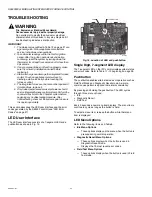
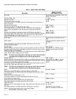
Page 24: ...ny troubleshooting procedure After troubleshooting check out the system again to be sure it is operating normally This section describes the LED user interface and the error codes generated by the S9240F control see LED Error Codes on page 27 LED User Interface The LED user interface consists of a 7 segment LED and a pushbutton as shown in Fig 15 Fig 15 Location of LED and pushbutton Single Digit ...

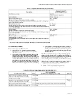
Page 25: ...y Remain in diagnostic recall mode Solid 3 horizontal bars Exit diagnostic recall mode Solid C for 10 seconds Clear error historyb b Clear Error History Once the button is released a blinking C displays for up to 10 seconds During this time you must press and release the button one additional time to confirm the action of deleting the error history If the IFC is in a lockout state the IFC proceeds...

Page 26: ...e LED display when the 2nd stage heat is active CFM of 1050 and flame current of 10 3uA NOTE The flame current displayed is the value read when the push button was pressed at the beginning of the LED display sequence H 2 Pause Display CFM e g A 1050 Pause Display Flame Current e g F10 3 Repeat Heating input Shows what furnace input percent 40 to 100 is currently operating the blower CFM and the fl...

Page 27: ...operation Vent Calibration C A L Pause Heat Pump heating stage Shows what stage of heat pump currently operating The display example in this table shows the LED display when the 1st stage heat pump is active with 950 CFM H 1 Pause A 9 5 0 Dehumidification mode Shows that the unit is providing dehumidification instead of straight cooling The display example in this table shows the LED display when ...

Page 28: ...e switch calibration Low pressure switch failed stuck Closed 224 Resume normal operation after fault removed High pressure switch failed stuck Open 225 Increase inducer RPM every few seconds If upper limit reached start pressure switch calibration High pressure switch failed stuck Closed 226 Wait for it to open then start calibration Low pressure switch opened in run or Trial for Ignition 227 Incr...

Page 29: ...ed when exiting lockout Inducer over current 294 Soft Lockout Send command to reset motor Error counter cleared when exiting lockout Rollout open or previously opened 200 Wait for rollout switch to close then enter Hard Lockout All error counters cleared after reset Hard Lockout Furnace size select missing or mis match with installed circulator motor BTU reading mismatch 202 Hard Lockout All error...

Page 30: ...S9240F2051 MODULATING INTEGRATED FURNACE CONTROL 69 2807 01 30 ...

Page 31: ...S9240F2051 MODULATING INTEGRATED FURNACE CONTROL 31 69 2807 01 ...

Page 32: ...CONTROL Automation and Control Solutions Honeywell International Inc 1985 Douglas Drive North Golden Valley MN 55422 customer honeywell com U S Registered Trademark 2013 Honeywell International Inc 69 2807 01 M S 03 13 Printed in United States ...

Reviews: