S9240F2051 MODULATING INTEGRATED FURNACE CONTROL
11
69-2807—01
CHECKOUT
Check out the integrated furnace control system:
— At initial installation of the IFC.
— As part of regular maintenance procedures.
— As the first step in troubleshooting.
— Any time work is done on the system.
Use the following procedures only for the integrated furnace
control; see individual component instructions for additional
checkout procedures.
Operation with Allied Communications
When configured in a communicating system, refer to the
Allied documentation for details of the IFC’s operating modes.
The following checkout and operational information applies to
conventional thermostat operations in a non-communicating
environment.
Check Normal Operation
1.
Turn on power to the appliance.
NOTE: Powering up or cycling power will generate the
Pressure Switch Calibration sequence prior to
responding to the call for heat.
2.
Reset the IFC by turning the thermostat to its lowest
setting and waiting five seconds.
3.
Set the thermostat to call for 1st stage heat. Make sure
the integrated furnace control sequences the system as
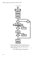
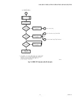
indicated in Fig. 9 on page 18 (Fig. 12 on page 21 for
single stage thermostat).
4.
Set the thermostat below the room temperature to end
the call for heat. The burner should go out; the induced
draft fan should provide postpurge time (20 seconds);
and after the delay time, the circulator should stop.
There are several modes of operation. They are discussed in
this section in the following order:
1.
2.
3.
Heat Mode:
a. “Normal Heat Mode - Conventional 2-Stage
Thermostat (standard 2-stage operation selected)”
b. “Modulating Mode - Conventional 2-Stage
Thermostat (special sequence selected)” on
page 13, or
c. “Normal Heat Mode - Conventional Single Stage
4.
5.
NOTE: Compressor heat, Ignition, Retry, Rollout circuit,
Limit switch, Pressure switches, HSI, Humidity
control, and Electronic air cleaner operation are
discussed beginning on page 13.
Pressure Switch Calibration
A system calibration sequence is required prior to normal use
and after AC power is cycled off then on. This process
establishes furnace operating parameters in the specific
installation and provides data to support robust system
operation. The calibration sequence may be repeated at other
times as required to help assure optimum performance.
Calibration is required during the initial start up of the furnace
installation in the field. All fuel, electrical, venting, condensate
drain piping (trap primed), combustion air supplies, as well as
conditioned air ducts and returns should be connected prior to
calibration.
NOTE: The calibration process takes 60 to 120 seconds
to complete successfully. The LED flashes “C A
L” during a the calibration cycle.
Successful Calibration
Calibration data is stored in volatile memory and is used to
determine furnace operation and control parameters in
heating mode. The IFC will not perform additional calibrations
unless required by changes in the appliance’s operating
conditions, if requested by the installer/service person, or by
cycling the power to the furnace.
Unsuccessful Calibration
If the inducer speed limits are reached, and calibration is
unsuccessful, the IFC proceeds to a 5 minute delay and
flashes the appropriate LED error code. The IFC repeats the
calibration sequence four times with a 5 minute delay in
between each try, and if still unsuccessful, the IFC moves to
Soft Lockout.
Calibration Initiation
Calibration initiates by:
• The IFC, on the initial call for heat after power-up.
• The installer/service person as part of the Field Test Mode.
See “Field Test Mode” on page 25.
• The IFC, whenever a venting condition change is detected
including:
— Low pressure switch fails to close during the wait for
low pressure switch to close time. Calibration takes
place immediately.
— Low pressure switch opens for longer than two
seconds during the heating cycle. Heating cycle
includes prepurge, HSI warm up, trial for ignition,
flame stabilization, and run states. Calibration takes
place immediately.
— High Pressure Switch fails to close or open during the
heating cycle at 100% firing rate operation. Calibration
takes place on the next call for heat.
— Ramp down low fire switch check fails. Calibration
takes place on the next call for heat.
The calibration process does not generate any error codes
other than the inducer or pressure switch calibration failures.
However, If either pressure switch closes before the
calibration starts and while the inducer RPM is zero (0), the
pressure switch error is generated.
At the end of a successful calibration, if a call for heat is still
present, the IFC skips the Prepurge and goes straight into HSI
warm-up. This speeds up the heating process and reduces
the excess purge.

