background image

S9360B, S9361B, S9370B, S9371B, S9380B, S9381B INTEGRATED WATER HEATER CONTROLLERS

69-1792—09

16

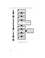
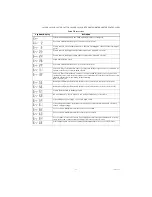
Fig. 11. Operating sequence - S936.

CALL FOR HEAT ACTIVE

(Temperature low)

1

PREPURGE

Draft source energized

(Combustion blower or damper)

2

SPARK GENERATOR POWERED

Pilot valve opens.

3

PILOT BURNER OPERATION

OR

4

Pilot burner does not light.

After retry delay system retries.

If retries exceed maximum, timed

lockout is entered.

Pilot burner lights.

Ignition module senses flame 

current and continues.

FLAME CURRENT SENSED

Spark generator off,

Main valve opens.

5

MAIN BURNER OPERATION

Ignition module monitors pilot flame

current.

6

CALL FOR HEAT INACTIVE

(Temperature at setpoint)

Valves close

7

POSTPURGE

Draft source de-energized after time.

(Combustion blower or damper)

8

POWER INTERRUPTION

System shuts off

PILOT FLAME FAILURE

Valves close, after recycle delay

system recycles. If recycles exceed

maximum, timed lockout is entered.

START

STAGE 1

PREPURGE

STAGE 2

TRIAL FOR IGNITION

STAGE 3

MAIN BURNER

OPERATION

STAGE 4

POSTPURGE

END

M24054

Summary of Contents for S9360B

Page 1: ...park Ignition Remote Display Water Heater Applications S9381B Direct Spark Ignition On board Display Water Heater Applications All models are enabled with EnviraCOM communication capability to support remote monitoring and diagnostics Limit rated Temperature Sensing Probe One or Two Sensor Models SPECIFICATIONS IMPORTANT The specifications given in this publication do not include normal manufactur...

Page 2: ...24 Vac 0 5 to 0 6 PF Pilot Valve Optional Full Load 2A at 24 Vac 0 5 to 0 6 PF In Rush 6A at 24 Vac 0 5 to 0 6 PF Hot Surface Igniter HSI Optional Full Load 4 5A at 120 Vac Warm up Time 18 seconds recommended for Norton igniter model 201 or 270 or equivalent Ambient Ratings Humidity 0 to 95 percent relative humidity noncondensing Operating Ambient Temperature 30 F to 150 F Shipping Ambient Tempera...

Page 3: ...ot reach them The controls should be high enough above the bottom of the cabinet so they will not be subjected to flooding or splashing during normal cleaning procedures If necessary shield the controls to protect them from splashing water A NEMA 4 enclosure is recommended High Humidity or Dripping Water Over time dripping water or high ambient humidity can create unwanted electrical paths on the ...

Page 4: ...ent temperature at the control locations will not exceed the rating of the control If the appliance normally operates at very high temperatures insulation shielding and air circulation may be necessary to protect the controls Proper insulation or shielding should b provided by the appliance manufacturer make sure adequate air circulation is maintained when the appliance is installed ...

Page 5: ...y application but especially so in commercial agricultural and industrial applications because 1 In such applications particularly commercial the equipment can operate 100 000 to 200 000 cycles per year Such heavy cycling can wear out the gas control in one to two years A normal water heater application for which the controls were intended typically operate fewer than 10 000 cycles per year 2 Expo...

Page 6: ...ath or property damage Disconnect the power supply before making wiring connections to prevent electrical shock or equipment damage Check the wiring diagram furnished by the appliance manufacturer if available for circuits differing from the wiring hookup shown in Fig 4 to 6 Carefully follow any special instructions affecting the general procedures outlined below WATER HEATER CONTROL BOX M24229 5 ...

Page 7: ...ning Module Connectors Connect remaining system components to the ignition module terminals as shown in the appropriate wiring diagrams Fig 4 to 6 Connect Igniter HSI Models Prepare wiring harness 1 Use wire suitable for the temperatures near the HSI igniter 2 Use wire suitable for the voltage ratings of the specific igniter 3 Attach connector per Table 4 HSI Specific Connectors Connect Gas Contro...

Page 8: ...9371B S9380B S9381B INTEGRATED WATER HEATER CONTROLLERS 69 1792 09 8 Transformer Add current ratings of module gas control vent damper and any other components of the control system to determine transformer size requirements ...

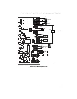
Page 9: ...agrams see Fig 4 to 6 Fig 4 Spark ignition wiring S936X M24216B CIRCULATOR SPARK IGNITER FLAME SENSE INDUCER L1 L2 GND GND 24 VAC TRANSFORMER DAMPER ENVIRACOM DIAGNOSTIC SENSOR 1 SENSOR 2 ENVIRACOM DISPLAY GAS CONTROL MV PV PV MV PRESSURE SWITCH LIMIT SWITCH OPTIONAL DEPENDING ON CONFIGURATION 1 1 1 1 ...

Page 10: ...S 69 1792 09 10 Fig 5 Direct spark ignition S938X M27380 INDUCER SPARK IGNITER FUME SENSE L1 L2 GND DAMPER ENVIRACOM DIAGNOSTIC SENSOR 1 SENSOR 2 E COM GAS CONTROL MV MV PRESSURE SWITCH LIMIT SWITCH OPTIONAL DEPENDING ON CONFIGURATION 1 1 C R D TSTAT SWITCH 1 24 VAC TRANSFORMER ...

Page 11: ...ER CONTROLLERS 11 69 1792 09 Fig 6 Hot surface ignition wiring S937X SENSOR 1 SENSOR 2 GAS CONTROL MV MV PRESSURE SWITCH LIMIT SWITCH M24218A ENVIRACOM DISPLAY ENVIRACOM DIAGNOSTIC 24 VAC TRANSFORMER L2 L1 GND FLAME SENSE HOT SURFACE IGNITER CIRCULATOR INDUCER GND ...

Page 12: ...OM R 2 3 of 3 ECOM C 3 EnviraCOM Diag White 1 of 3 Pen Diagnostic Tool with 0 1 in spacing ECOM Data 1 2 of 3 ECOM R 2 3 of 3 ECOM C 3 Transformer Primary White 1 of 3 Molex 50 81 1030 L1 2 of 3 Earth Ground 3 of 3 Neutral Transformer Secondary White 1 of 2 Molex 50 81 1020 24 Vac Input 2 of 2 Earth Ground Control White 1 of 9 Molex 50 81 1090 Pressure Switcha 2 of 9 Pilot Valvea 3 of 9 Pressure S...

Page 13: ...d Display To discourage unauthorized changing of settings a procedure to enter the adjustment mode is required To enter the adjustment mode press the UP DOWN and I buttons see Fig 1 simultaneously for three seconds Press and release the I button until the parameter requiring adjustment is displayed Connection Pin Mating Plug Description Line Voltage Input White 1 of 4 Molex 50 81 1040 L1 2 of 4 Ea...

Page 14: ...See Troubleshooting section to assist in determining system operation LOCATION AND MOUNTING Sensing Bulb s The water heater manufacturer usually provides a tapping for the sensing bulb at a point where average water temperature can be measured Some water heaters use two 2 sensors one limit rated near the center or bottom of the tank the other non limit rated near the top See Fig 8 Follow the heate...

Page 15: ...ing must comply with local codes and ordinances regarding wire size type of insulation enclosure etc OPERATION AND CHECKOUT Operation The S9360B S9361B S9370B S9371B S9380B and S9381B continuously monitor the temperature of the water heater and enable the burner based on this temperature data In general when the temperature is low a Call for Heat is activated which activates the ignition portion o...

Page 16: ...ed Pilot burner lights Ignition module senses flame current and continues FLAME CURRENT SENSED Spark generator off Main valve opens 5 MAIN BURNER OPERATION Ignition module monitors pilot flame current 6 CALL FOR HEAT INACTIVE Temperature at setpoint Valves close 7 POSTPURGE Draft source de energized after time Combustion blower or damper 8 POWER INTERRUPTION System shuts off PILOT FLAME FAILURE Va...

Page 17: ...TOP SPARKING FLAME STABILIZATION TURN MAIN VALVE ON RUN POSTPURGE TIME OUT TIME OUT CALL FOR HEAT LOST OR LIMIT OPEN RETRY DELAY RECYCLE DELAY DAMPER PRESSURE SWITCH OPEN CHECK FLAME POST TRIAL FLAME DEB ON FLAME LOST B CALL FOR HEAT BIAS DONE LIMIT SWITCH CLOSE SWITCH OPEN DRIVE DAMPER INDUCER WAIT FOR SWITCH CLOSE SWITCH OPEN SWITCH CLOSE M29795 FLAME SENSED FLAME PROVED TIME OUT B A FLAME DEB O...

Page 18: ...ld if necessary If flame rod or bracket are bent out of posi tion restore to correct position STEP 3 Check spark ignition circuit WARNING The ignition circuit generates over 10 000 volts and electrical shock can result Energize the module and listen for the audible sparking noise When operating normally there should be a buzzing noise that turns on and off twice per second for a duration of 1 7 se...

Page 19: ...ilure open or short connection increased connection resistance dual sensor mismatch or failure of A D conversion invalid offset or gain too many failures during A D conversion Atmospheric Damper End Switch failed to close end switch contacts stuck open Atmospheric Damper End Switch failed to open end switch contacts stuck closed Flame Rod shorted to burner ground AC line frequency error signal is ...

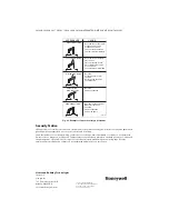
Page 20: ... may pose a safety risk Tamper evident tape has been placed on the bulk pack box to indicate if the package was opened Do not accept or use product received with damaged or missing tape Reverse engineering or modification of device is not permitted and may pose a safety risk LAZY YELLOW FLAME WAVING BLUE FLAME NOISY LIFTING BLOWING FLAME HARD SHARP FLAME SMALL BLUE FLAME CHECK FOR LACK OF GAS FROM...

Reviews: