3
DVI 980/982
3. Lock out and reset
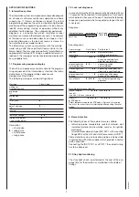
The unit can be reset or brought into lock out mode in two
different ways:
Internal (optional)
In the lock out case the unit can be reset by pushing the
reset button meaning a new start-up cycle is performed.
External
Instead of using the reset lock out button the same
function can be achieved by using an external button which
connects terminal X2/12 with X2/9 (see also circuit and
block diagram).
Models with volatile lock out also can be reset by a short-
time interrupt of the supply line.
If the pushbutton (internal or external) is pressed during
normal operation or during the start sequence for more then
3 sec. and afterwards released, the control box will perform
a shutdown.
Please note
The unit can only be brought to lockout mode or
be reseted if power is applied to the unit.
Don't apply to units with volatile lock out.
4. Low-voltage protection
The mains voltage has to be more than 193 V
eff
in order to
allow the unit to perform a start-up.
The mains voltage is not only monitored in the start-up
phase but also permanently during operation. If the
voltage drops below < 175 V
eff
during start-up or run time
the control box proceed to safety shut-down and goes
into a waiting status. If the voltage rises again, the control
box performs automatically a start-up as soon as the
mains voltage is > 193 V
eff
.
5. Safety
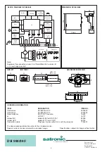
The design and control sequence of the DVI980/982 controls
will comply with the currently applicable standards and
regulations (see also TECHNICAL DATA).
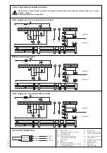
6. Mounting and electrical wiring
The DVI 980/982 is put directly on the solenoid valve.
Molex plug connector 3003 for:
– Power supply line
– Control thermostat RT
– Air proving switch LW
– Motor M
– External lock out signal
– Safety temperature delimiter STB
– External reset and lock out button
Counterpart:
– Molex plug connector 3001
General
The control box and the sensor shall not be exposed to
excessive vibrations.
7. Model functions
The following functions are configured by factory
Model 01:
•
with air proving switch
•
IR-data transmission over Palm Pilot, PC or hand-held
•
non volatile lock out, no reset with interrupt of the supply
line
•
direct lockout after loss of flame during operation
•
direct lockout if no flame established after safety time
•
with internal reset button
•
without potential free output for flame signal
•
Circuit diagram:
"valve supply over air proving switch
contact", variation A, see page 5)
Model 02:
•
with air proving switch
•
IR-data transmission over Palm Pilot, PC or hand-held
•
non volatile lock out, no reset with interrupt of the supply
line
•
altogether 2 times recycling if no flame established after
safety time or loss of flame during operation
•
without internal reset button
•
potential free output for flame signal
•
Circuit diagram:
"valve supply not over air proving
switch contact", variation A, see page 5)
•
with internal lock out lamp (LED)
Model 05:
•
with air proving switch
•
IR-data transmission over Palm Pilot, PC or hand-held
•
volatile lock out, reset with interrupt of the supply line
•
altogether 2 times recycling if no flame established after
safety time or loss of flame during operation
•
without internal reset button
•
potential free output for flame signal
•
Circuit diagram:
"valve supply over air proving switch
contact", variation A, see page 5)
•
with internal lock out lamp (LED)


