4
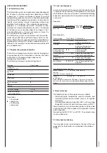
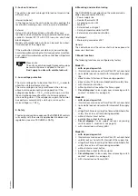
DVI 982/982
INSTALLATION INSTRUCTIONS AND MAINTENANCE
1. Important notes
– The controls must be installed by qualified personnel
only. The relevant national regulations have to be
observed.
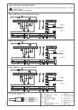
– On commissioning the wiring has to be carefully checked
according the appropriate diagram, Incorrect wiring can
damage the unit and endanger the installation.
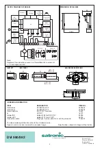
– The fuse rating has to ensure that the limits specified in
TECHNICAL DATA will not be exceeded. If these
precautions are not observed, the effect of a short circuit
can cause severe damage to the control and installation.
– For safety reasons a minimum of one control shutdown
per 24 hours has to be observed.
– Disconnect the mains before the control box is plugged
in or out.
– The control box is a safety device and must not be
opened!
2. Function control
For safety reasons the flame detection system should be
tested on commissioning the installation as well as after a
service or longer shut-down.
a) Start-up with closed gas valve
– for direct lockout operation, after safety time is over
the unit has to go into lock out mode!
– for recycling operation (max. recycling limited) carry
out a re start-up.
b) Normal start-up, when burner is running, close gas valve
– for direct lockout operation, after loss of flame the
control box has to go into lockout mode!
– for recycling operation (max. recycling limited) carry
out a re start-up.
c) Normal start-up, during pre-purge or operation, interrupt
the air proving switch
– for direct lockout operation, the control box has to go
into lockout mode immediately!
– for recycling operation (max. recycling limited) carry
out a re start-up.
d) Bridged air proving switch before start
– the fan motor switches on for approx. 2 - 3 sec.,
followed by a lockout. After 10 sec., this quick lockout
is resetted by the control box and a second start
attempt follows (fan motor switches on for approx.
2 - 3 sec.). A standard lockout appears if the air
proving switch (LW) contact is still in it’s closed
position (e.g. welded contacts). Has the air proving
switch (LW) changed to it’s open position in the
meantime (e.g. by a run down motor), a normal start
sequence follows.
3. Fault finding
The built-in information system facilitates the trouble
shooting in the case of problems occurring during start-up
or during operation.
A list of possible lock out messages can be found in
APPLICATION FEATURES chapter 1.2.
Please note:
The control box is locked in lock out mode
and the reason for the lock out is displayed
until the control box is reset, either by an
internal or external reset (see also subject
“3. Lock out and reset“).
Interrupting the supply line (by models with non volatile lock
out) may not reset a lock out. Therefore, by applying power,
the fan motor switches on for 2-3 secs. before the control
box goes to lock out again in cause of the last lock out.
Error
Possible fault
Burner not working
- Thermostat circuit open
- Faulty electrical wiring
- Mains voltage < 193 V
Fan motor starts for a short - Control box has not been reset
period of time, control box
- Air proving switch not in open
goes to lock out
position
Control box locks out or
- Air proving switch has not closed
recycled during pre-purge
within 60 sec.
- Air proving switch has re-opened
Control box locks out or
- Air proving switch open
recycled at the end
- Flame signal (stray light)
of pre-purge
Burner starts,
- No ignition or no gas
flame not established,
after safety time
lock out or recycling
Burner starts,
- No or to low flame signal (flame
flame established,
does not stick, bad insulation of
after safety time
the ionisation probe, bad connec-
lock out or recycling
tion to frame ground)
- Insufficient light on IRD or UVD
- Sensitivity adjustment
to low on IRD


