background image

6

A Honeywell Company

Satronic AG
Honeywell-Platz 1
Postfach 324
CH-8157 Dielsdorf

DVI 980/982

HOLDER M 93 FOR IRD

35

3

14

4.5

26

15.1

48

17

ø20.5

4

+

ORDERING INFORMATION

ITEM

DESIGNATION

ITME NO.

Control box

DVI 980 Mod. 02

0390602

Control box

DVI 980 Mod. 05

0390605

Flame detector

IRD 1020.1 D end-on

16552

or

UVD 971

16722

Holder IRD

Holder M 93 for IRD 1020.1

59093

Holder UVD

Holder M 74 for UVD 971

59074

Connection cable

Plug-type, 3-core cable, 0.6 m with tag wire end

7236001

The above ordering information refers to the standard version.
Special versions are also included in our product range.

Specifications subject to change without notice

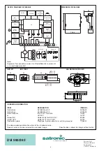
BLOCK DIAGRAM DVI 980/982

1

2

7

4

5

6

10

8

11

12

9

Flame

amplifier

Reset

µC

Reset and

lock out

Mains

monitoring

Power

supply

monitoring

rs

RV1

RV2

RS

lock out lamp

(LED)

 Information

system

EEPROM

Oscillator

Power

supply

µC

Watchdog

valve supply

UVD 971

IRD 1020.1

29

50

UVD = 29

IRD = 44

21,8

ø13,5

UVD = 89

IRD = 104

29

21,8

Flame

signal

output

Ignition

spark

generator

rv1

X8

X7

X3

X9

X5

X6

230V DC

230V DC

230V DC

230V DC

230V DC

V1

V2

V1

V2

V1

V1

Variante A

Variante B

X2

Note:
Equipment for connection version A is fitted differently to version B.
–> no exchange possible!

31.5

60

113

106.5

DIMENSION DVI 980/982

+

-

Summary of Contents for Satronic DVI 980

Page 1: ... lock out blocked after loss of flame during operation recycling numbers eligible or lock out blocked without flame establishment after safety time with or without internal reset button potential free output for flame signal with or without lock out lamp LED DVI 980 982 Honeywell Nr S4865 Gas Burner Safety Control For 1 or 2 stage forced draught and atmospheric gas burners with DC valves Possible ...

Page 2: ...gnoses In case of a failure the LED is permanently illuminated Every 10 seconds the illumination is interrupted by a flash code whichindicatesthecauseoftheerror Thereforethefollowing sequence is performed which is repeated as long as the unit is not reset Sequence illuminated phase dark phase Flash Code dark phase for 10 sec for 0 6 sec for 1 2 sec Error diagnosis Error message Flash Code Possible...

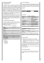
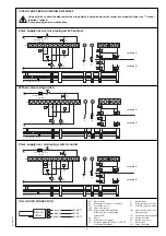
Page 3: ...I 980 982 is put directly on the solenoid valve Molex plug connector 3003 for Power supply line Control thermostat RT Air proving switch LW Motor M External lock out signal Safety temperature delimiter STB External reset and lock out button Counterpart Molex plug connector 3001 General The control box and the sensor shall not be exposed to excessive vibrations 7 Model functions The following funct...

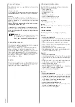
Page 4: ...ec this quick lockout is resetted by the control box and a second start attempt follows fan motor switches on for approx 2 3 sec A standard lockout appears if the air proving switch LW contact is still in it s closed position e g welded contacts Has the air proving switch LW changed to it s open position in the meantime e g by a run down motor a normal start sequence follows 3 Fault finding The bu...

Page 5: ...e tlw Max reaction time for air proving switch tv1 Supervised pre purge time tvz Pre ignition time tz Ignition time total ts Safety time tv2 Delay 2nd stage HS Mains switch EV External reset and lock out button RT Control thermostat LW Air proving switch STB Safety temperature delimiter Using wire link for application without STB M Motor SA External lock out signal IS Ionisation probe IRD 1020 1 U...

Page 6: ...e standard version Special versions are also included in our product range Specifications subject to change without notice BLOCK DIAGRAM DVI 980 982 1 2 7 4 5 6 10 8 11 12 9 Flame amplifier Reset µC Reset and lock out Mains monitoring Power supply monitoring rs RV1 RV2 RS lock out lamp LED Information system EEPROM Oscillator Power supply µC Watchdog valve supply UVD 971 IRD 1020 1 29 50 UVD 29 IR...

Reviews: