SC Series Instruction Manual - Model SC500 page 29
Chassi
s Models
4
4.3.6 Case Removal
Step 1: Remove the cable shield connection screw on the rear of the instrument.
Step 2: Remove the two Phillips-head screws that secure the front panel.
Do not
disconnect the front panel’s connecting cable.
Step 3: The front panel and circuit boards will slide out of the front of the case as a
unit.
Installation is the reverse of removal.
4.3.7 Internal Arrangement
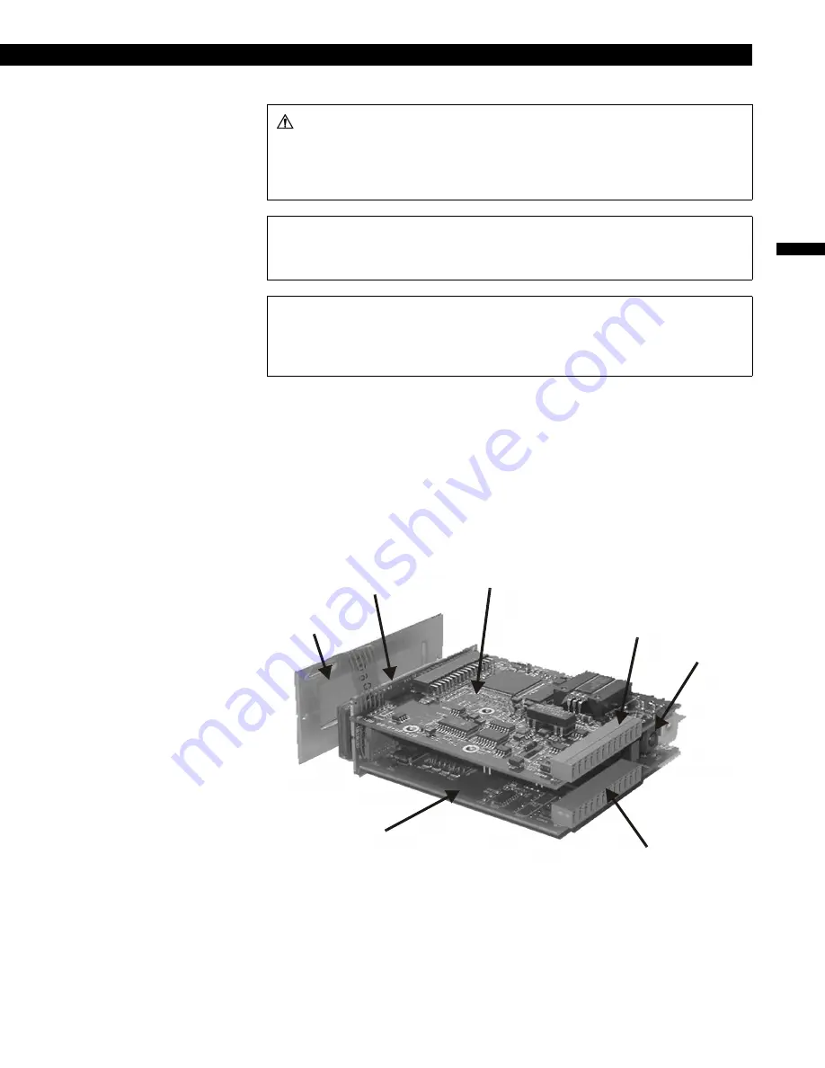
The figure below shows the names and locations of the printed circuit boards.
Figure 4-3: Internal Arrangement of Model SC500
WARNING
Disconnect the power cord and all cables from the instrument before attempt-
ing to remove the case.
Failure to comply with these instructions could result in death or serious
injury.
CAUTION
Use a #0 Phillips screwdriver on the black screws to avoid damaging them.
Failure to comply with these instructions may result in product damage.
CAUTION
Ensure normal ESD (Electrostatic Discharge) precautions are followed when
handling circuit boards.
Failure to comply with these instructions may result in product damage.
Display Board
Front Panel
Assembly
Main Circuit Board
Input Channel
Connector
Power
Connector
Options Connector
Options Circuit Board
Summary of Contents for SC500
Page 8: ...page 8 008 0671 00 ...
Page 14: ...page 14 008 0671 00 ...
Page 18: ...page 18 008 0671 00 ...
Page 24: ...page 24 008 0671 00 ...
Page 38: ...page 38 008 0671 00 ...
Page 42: ...page 42 008 0671 00 ...
Page 50: ...page 50 008 0671 00 ...
Page 72: ...page 72 008 0671 00 ...
Page 82: ...page 82 008 0671 00 ...
Page 90: ...page 90 008 0671 00 ...
Page 116: ...page 116 008 0671 00 ...
Page 126: ...page 126 008 0671 00 ...


