SC Series Instruction Manual - Model SC500 page 53
Str
ain
-G
ag
e In
pu
t C
han
ne
l
10
10.2.1 Strain-Gage
Transducers
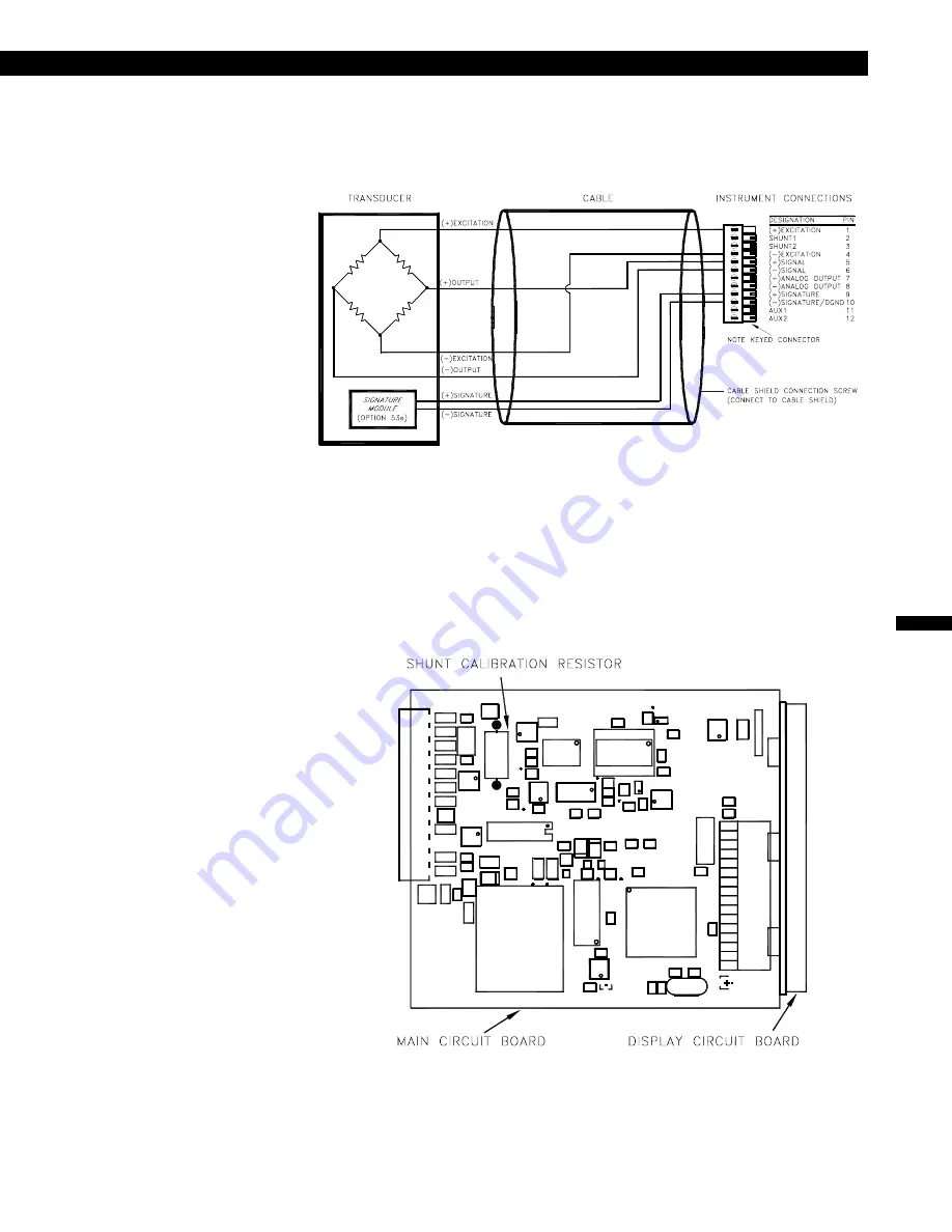
Use the following wiring diagram when connecting an unamplified, strain-gage
transducer to a Strain-Gage Input channel.
Figure 10-1: Unamplified Transducer Connection to Strain-Gage Input Channel
If the Shunt Calibration method is used to calibrate the instrument to the trans-
ducer, the shunt calibration resistor inside the instrument is placed across the
(-)Excitation and (-)Output pins during Shunt Calibration functions. Normally, the
instrument has a shunt calibration resistor of 59000 (59K) ohms installed. The
shunt resistor’s ohmic value used to generate the Shunt-Calibration Output is
given on the transducer’s Certificate of Calibration. If your transducer and instru-
ment were purchased at the same time, the correct shunt resistor for your trans-
ducer has been installed.
Figure 10-2: Shunt Calibration Resistor Location
Summary of Contents for SC500
Page 8: ...page 8 008 0671 00 ...
Page 14: ...page 14 008 0671 00 ...
Page 18: ...page 18 008 0671 00 ...
Page 24: ...page 24 008 0671 00 ...
Page 38: ...page 38 008 0671 00 ...
Page 42: ...page 42 008 0671 00 ...
Page 50: ...page 50 008 0671 00 ...
Page 72: ...page 72 008 0671 00 ...
Page 82: ...page 82 008 0671 00 ...
Page 90: ...page 90 008 0671 00 ...
Page 116: ...page 116 008 0671 00 ...
Page 126: ...page 126 008 0671 00 ...


