background image


19 

CAMERA SETUP                              PAGE : 001 
Cam      Protocol     Port           B_rate           Alarm 
0001     S2              PORT 1     9600             OFF 
0002     S2              PORT 1     9600             OFF


0009     -   -               -    -          9600             OFF


- - - -     -   -               -    -          9600             OFF


3999     S2              PORT 1     9600             OFF


OFF :del    ENTER : save & exit   ESC : cancel 

TIME / DATE   Setup 

Display               : ON / 

OFF 

Date Format       : Asia 

/ US/ EURO  2005/JAN /18


Time Format      : 12

 / 24   08: 59 : 04


Day Light Saving : ON

/ OFF 

Day Light Saving


Save and Exit 


Day   Light   Saving   Setup 

Date                             Time 

Start  : 01 / 01                          00 : 00 
END  : 01 / 01                          00 : 00 

Save and Exit 


Device         : Select Device to be controlled ( 

DVR

 / Alarm / 

AUX IN / AUX IO / None

 ) 

Baud Rate   : Communication speed ( 2400 / 4800 / 

9600

 / 19200 / 38400 / 57600 / 11.5K / 230K ) 

Save and Exit Press         key to exit without saving the data. 

 
Camera

 (

Shft + Menu


è

Camera

)


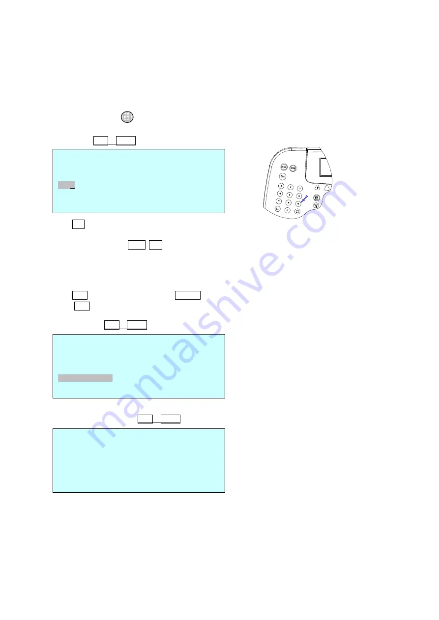
Press No. key or twist zoom handle on the first column to enter setup mode. 

Input camera ID using numeric keys or twist the zoom handle to increase/ decrease the ID.  

Push the joystick to the Right/ Left to select next/ previous item and select the protocol to be used by 

twisting zoom handle. ( EZ / HWL / S2 / S2e / Pelco P/ Pelco D) 

Push the joystick to right and set the baud rate by twisting the zoom handle. 
Select option to receive or not receive alarms from the dome. 

(Alarm OFF : simplex,  Alarm ON : half-duplex) 

Press OFF key to delete the dome ID. ENTER key to save & exit. 

Press  ESC key to exit without saving. 
 

Time/Date

 (

Shft + Menu


è

Time/Date

)


Day Light Saving

 (

Shft + Menu


è

Time/Date 

è

Day light Saving

)


Select Day Light Saving item and program the start and end date. 
Push the joystick to Right/ Left to select item and twist the zoom handle to increase/decrease the date and 
time. 
 

ESC 


Summary of Contents for ScanDome HTX-5000

Page 1: ...ScanDomeTM JOYSTICK CONTROLLER HTX 5000 Please read this manual thoroughly before use and keep it handy for future reference Rev 060210 Instruction Manual ...

Page 2: ... with arrowhead symbol within an equilateral triangle is intended to alert the user to the presence of uninsulated dangerous voltage within the product s enclosure that may be of sufficient magnitude to constitute a risk of electric shock to persons The exclamation point within an equilateral triangle is intended to alert the user to the presence of important operating and maintenance servicing in...

Page 3: ...Y CAUSE HARMFUL INTERFERENCE TO RADIO COMMUNICATIONS OPERATION OF THIS EQUIPMENT IN A RESIDENTIAL AREA IS LIKELY TO CAUSE HARMFUL INTERFERENCE IN WHICH CASE THE USER WILL BE REQUIRED TO CORRECT THE INTERFERENCE AT HIS OWN EXPENSE CAUTION CHANGES OR MODIFICATIONS NOT EXPRESSLY APPROVED BY THE PARTY RESPONSIBLE FOR COMPLIANCE COULD VOID THE USER S AUTHORITY TO OPERATE THE EQUIPMENT THIS CLASS A DIGI...

Page 4: ...ement of the obsolete outlet 10 Protect the power cord from being walked on or pinched particularly at plugs convenience receptacles and the point where they exit from the apparatus 11 Only use attachments accessories specified by the manufacturer 12 Unplug this apparatus during lightning storms or when unused for long periods of time 13 Refer all servicing to qualified service personnel Servicing...

Page 5: ...wo DVR configuration 10 2 1 4 Multiple Joystick Controller configuration 11 2 2 Termination Dip Switch Settings 12 CHAPTER 3 OPERATION 14 3 1 Basic operation 14 3 1 1 MASTER CONTROLLER MODE 14 3 2 Configuration the controller 16 3 3 Operation the controller 22 3 3 1 Selection of the dome camera ID of the Dome Camera 22 3 3 2 Selection of the DVR ID of the DVR 22 3 3 3 Key description of the contro...

Page 6: ...presets which are immediate camera call ups of preset position view with automatic zoom and focus Program 4 patterns which comprise a sequential series of pan tilt zoom and focus movements from a single camera One define continuous rotation with 16 scans 8 tours consisting of 64 presets patterns scans and alternate tours It is expandable to over 400 functions with nested tours Global preset recall...

Page 7: ...ke sure all listed items are included in the box Some optional items may not be included in the box Contents of Joystick controller box Joystick controller 1 Junction box 1 8 pin cable 1 M4 Self tapping screws 1 Instruction manual 1 12VDC SMPS 1 ...

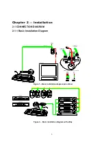
Page 8: ...4V POWER TXB TXA RXB R XA FGND A C AC TXB TX RXA RX RXB RX TXA TX RS 422 HALF DUPLEX MODE RS 485 or 4 ALARM INPUT 1 AUX OUTPUT RXA RXB TXA TXB TXB TXA RXB RXA TXA TX TXB TX SW1 Chapter 2 Installation 2 1 CONNECTION DIAGRAM 2 1 1 Basic Installation Diagram Figure 1 Basic installation diagram w o J Box Figure 2 Basic installation diagram with J Box ...

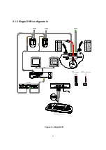
Page 9: ...RS 422 HALF DUPLEX MODE TXA TX RXB RX RXA RX TXB TX FGND AC AC TXB TXA RXB RXA RXA RXB TXA AC AC TXB VIDEO Tx DOME1 Tx DOME1 4 ALARM INPUT RS 422 FULL DUPLEX MODE 1 AUX OUTPUT J4 ALARM2 1 COM B 2 NC B 3 NO B 4 GND 5 ALARM8 6 ALARM7 7 ALARM6 8 ALARM5 J2 ALARM1 1 COM A 2 NC A 3 NO A 4 GND 5 ALARM4 6 ALARM3 7 ALARM2 8 ALARM1 2 1 2 Single DVR configuratoin Figure 3 Single DVR ...

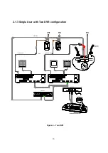
Page 10: ...24V AC 24V POWER POWER AC 24V BNC AWG 24 SW1 1 AUX OUTPUT 4 ALARM INPUT FGND AC AC TXB TXA RXB RXA RXA RXB TXA AC AC TXB VIDEO Tx DOME1 Tx DOME1 4 ALARM INPUT 1 AUX OUTPUT Camera 1 16 Camera 17 12 15 2 1 3 Single User with Two DVR configuration Figure 4 Two DVR ...

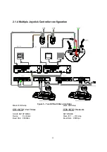
Page 11: ...1 AWG 24 BNC AC 24V POWER POWER AC 24V AC 24V POWER 1ST MAIN MONITOR 2ND MAIN MONITOR SPOT MONITOR 2 1 4 Multiple Joystick Controller configuration Figure 5 Two DVR with Slave Controller Master K B Setup Slave K B Setup Shft Menu èPort èSlave Shft Menu èNetworks SLAVE SETUP MENU NETWORKS Device Controller Slave ID 1 ID setup Baud Rate 9600bps Baud Rate 9600bps ...

Page 12: ...n ON SW1 Termination ON S1 DOme1 port Termination On S4 DVR port Termination On S3 Dome2 Termination ON SW1 Termination ON TERMINATION ON 2 2 TERMINATION DIP SWITCH SETTINGS The first and last devices in an installation dome and joystick controller must have the data line terminated by setting the DIP switch Without proper termination there may be control signal errors Total length of the cable fo...

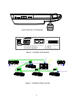
Page 13: ...RM IN ATIO N Tx Tx Rx Rx RS 485 RS 422 DC 12V S8 OFF M A STER O N SLAV E S4 DVR Port Termination ON DATA1 DATA1 IN OUT S5 Slave port termination ON Last DVR DVR2 DVR1 DVR Termination ON S8 Slave mode ON S8 Slave mode ON S8 Slave mode ON SW1 Termination ON S1 Dome1 Port Termination ON SW1 Termination ON Figure 7 Rear View of the Keyboard Figure 8 Termination and ID Switches Figure 9 Termination of ...

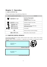
Page 14: ...menu items Joystick down Finish editing title Zoom handle twist Change value Increase Decrease Enter editing title mode SHFT Joystick Turbo speed ESC Escape from the menu without change Home or Off button Delete value or name of the field 3 1 1 MASTER CONTROLLER MODE As the DIP s w position 8 Off the joystick controller works as master controller Position 8 ON controller will work as slave control...

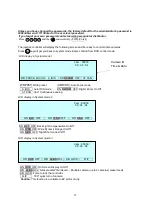
Page 15: ... to control dome cameras Press key will get you back to system mode dome control from DVR control mode LCD display in System mode 1 WR PRST Write preset A FOCUS Auto Focus mode A IRIS Auto IRIS mode ON DZOOM OFF Digital Zoom On Off AT PAN 360 Continuous panning LCD display in System mode 2 ON BLC OFF Back Light Compensation On Off ON WDR OFF Wide Dynamic Range On Off ON D N OFF Night Shot mode O O...

Page 16: ...screen will be shown following DVR mode LCD display in DVR mode 1 Press key to go back to the system mode from the DVR control mode 3 2 CONFIGURATION THE CONTROLLER If the user needs to setup the network change passwords or perform special tasks such as Uploading and Downloading programmed data from the dome cameras hold down key and then press key Shft Menu You will see the following menu Joystic...

Page 17: ... changing setup and programming enabled Password Enter current admin s password New Password Enter 1 8 digits new password Confirm Password Confirm 1 8 digits new password Note Factory default Administrator s password is 9999 Enter and user password is 1111 Enter If you forget your own password contact service personnel or distributor Save and Exit Save the programmed data and return to the previo...

Page 18: ...mmunication speed 2400 4800 9600 19200 38400 57600 11 5K 230K Save and Exit Press key to exit without saving the data Slave Shft Menu èPORT SETUP MENUèSlave KBD Device Select Device to be controlled Controller None Baud Rate Communication speed 2400 4800 9600 19200 38400 57600 11 5K 230K Save and Exit Press key to exit without saving the data DVR SETUP MENU Shft Menu èPORT SETUP MENUèDVR Device Se...

Page 19: ...o key or twist zoom handle on the first column to enter setup mode Input camera ID using numeric keys or twist the zoom handle to increase decrease the ID Push the joystick to the Right Left to select next previous item and select the protocol to be used by twisting zoom handle EZ HWL S2 S2e Pelco P Pelco D Push the joystick to right and set the baud rate by twisting the zoom handle Select option ...

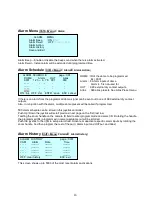
Page 20: ...resets See Alias Preset menu If there is an alarm from the programmed dome signal can be sent out to one of 999 external dry contact outputs Also in conjuction with the alarm multiple dome presets will be called if programmed 500 alarm schedule can be stored in this joystick controller Push Up Down the joystick will scroll previous next page on the first last row Twisting the zoom handle on the ca...

Page 21: ...page 15 MAIN MENU screen Night Shot Setup Shft Menu è Schedule è Night Shot Night shot option is enabled disabled ON by On time and Off Time can be setup using Night shot enable option changes low light sensitivity by removing IR cut filter from the camera lens If the option is enabled the controller sends the same control command to all the cameras attached on the control line It is the same effe...

Page 22: ... Camera Menu Access Allow camera menu in the Slave controller Clear saved Data Clear all data in the Slave controller 3 3 OPERATION THE CONTROLLER 3 3 1 Selection of the dome camera ID of the Dome Camera There are three ways for dome camera selection and Next or Prev With these selections the keyboard controller has the full control of the selected dome camera 3 3 2 Selection of the DVR ID of the ...

Page 23: ...t or tour programming mode the operator can review the existing preset selected by cursor by pressing this key Tour Pressing Tour will bring up the tour programming menu directly Recalls programmed presets or functions sequentially Ex 1 8 Tour Pattern Pressing Ptrn will bring up the pattern programming menu directly Repeats the selected pattern of the current dome camera Ex 1 4 Ptrn Auto Scan Pres...

Page 24: ...aying Rewind Play video backwards at high speed Pressing the button again toggles the playback speed from and Fast Forward Play video forward at high speed Pressing the button again toggles the playback speed from and Search Search the recorded image in Playback mode Help Change the image information display Date Channel Events etc Menu Enter the Quick Setup screen You will need to enter the admin...

Page 25: ...ol system Check that the dome camera IDs are set properly See Figures 1 to 9 Check the polarity of the data line Camera number does not match the multiplexer number Check the camera ID and insert the BNC cable into the proper input of the multiplexer Forgot password Consult your supplier distributor or service Center Multiplexer DVR can t work with the Joystick controller Check that the data cable...

Page 26: ... Slave Controller Connection Max 7 Multiplexer Connection Max 255 Zoom Camera Max 255 DVR Connection Max 100 Protocol S S2E Pelco Protocol D P Time Date Real Time Clock Schedule MECHANICAL Dimension 390x190x97 Unit mm Unit Weight Approx 1 2 kg Shipping Weight Shipping Size ENVIRONMENT Operating temperature 0 C to 50 C 32 F to 122 F Operating humidity 0 to 90 RH non condensing Storage temperature 2...

Reviews: