Hydraulic Components
SDC / DHC
242 EN2H-0221GE51
R0808
Bus test
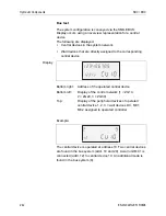
The system configuration is conveyed via the SMILE BUS.
Display occurs using an overview representation for a central
device.
The following are displayed:
•
Central devices in the system network
•
Wall devices that are directly assigned to the corresponding
central device
Bottom right: Address of the operated central device
Bottom left:
Display of the control network (1 = ZG10,
2 = ZG20, 3 = ZG30)
Top:
Display of the peripheral devices of operated
central device 1, 2, 3 = wall devices DC, MC1,
MC2 assigned to operated controller
Example:
The central device is operated at address 10. Two central devices
are found in the bus system (addr. 10 and 20). A wall unit MC1 is
connected (addr. 12) to central device 10. An additional mode is
found in the bus system (9).
Display

