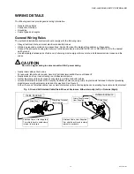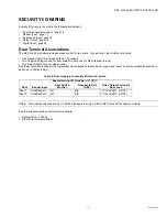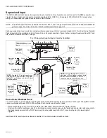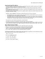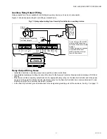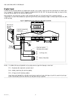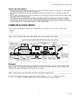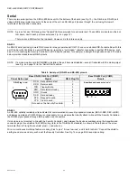
SEC-H-600 SECURITY CONTROLLER
95-7759—07
12
BOARD LAYOUT
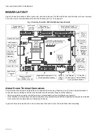
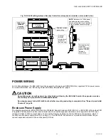
Figure 4 shows the location of LEDs, option slots, and other features of the SEC-H-600 Security Controller, with cover removed.
For a side view of communications ports and other features, see Fig. 15 on page 26.
Fig. 4. Security Controller (SEC-H-600) board layout details.
About Screw Terminal Connectors
Screw-terminal connectors are shipped loose in a separate hardware bag. If desired, you can make wiring terminations to
connectors
before
installing on the Security Controller circuit board pins. Please note the following:
• When you install a connector onto the board pins, terminal labels (on the circuit board) are
covered
.
• Once installed, removal of larger connectors (readers, relay outputs) may be difficult, especially if wiring has been landed.
Here, removal is recommended only if replacing the device.
In general, it may be easiest to wire to
loose
connectors (held next to pins), then install them after completing.
(one 4-position connector)
Option Slot 1 Area
Option Slot
Connectors
NiMH battery
pack Connector
(see Fig. 15 on
page 26)
Option Slot 2 Area
Earth Ground
Connector
Lug
Unsupervised Digital
Inputs (1—3)
One 4-position connector
12Vdc SLA
Backup Battery
Reader Input 2
(Wiegand 12V type)
Reader Input 1
(Wiegand 12V type)
LEDs for
relay
outputs
6 Pin End
Connector
(Expansion
Modules)
Digital Supervised Inputs (1—6)
Three 3-position connectors
Primary
Ethernet
(RJ-45)
LAN1
Security
Controller
NiMH
Backup
Battery and
Bracket
Mode Jumper
(for serial shell
access)
LAN1
STATUS
BEAT
LAN2
Status LEDs (visible with cover on)
6 Pin End
Connector
(Expansion
Modules)
includes
RS-485
Form-C Relay Outputs 1—4
Two 6-position connectors
RS-232
(DB-9)
COM1
each has one
7-position
connector
For External
15Vdc Supply
USB Port
(top board)
Future Use
LEDs for COM1
(RS-232) and
COM2 (RS-485)

