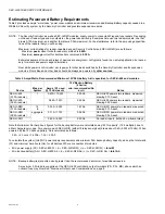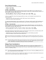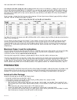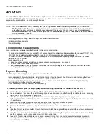
SEC-H-600 SECURITY CONTROLLER
95-7759—07
20
Relay Output
The SEC-H-600 controller has four (4) Form-C relay outputs, each rated to switch 24VAC/DC loads up to 3A. Output terminals
are located two 6-position connectors next to the card reader 2 input (see Fig. 4 on page 12). Terminals are labeled numerically 1
and 2 under one connector, and 3 and 4 under the other connector. Each has a NO
n
, C
n
, NC
n
terminal—for example NO3, C3,
NC3 for relay output 3.
NOTE: Relay outputs 1 and 2 are reserved for Door 1 and Door 2 strike control, respectively. Relay outputs 3 and 4 are avail-
able for general usage. For more details, see “Door Terminal Associations,” page 15.
Output Status LEDs
An LED status indicator for each relay output is located next to that output’s C (common) terminal on the circuit board—when lit,
that relay is energized. Therefore, a circuit wired through the normally open (NO
n
) terminal is On (closed) when the LED is lit,
and Off (open) when the LED is not lit.
Door Strike Wiring
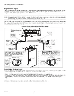
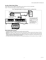
Typical “fail secure” door strike wiring, in this case for Door 1 using relay output 1, is shown in Figure 10 below.
Fig. 10. Relay output wiring from Security Controller to door strike (fail-secure).
GN
D
DC+
AX
3
AX
1
D1
AX
2
D0
+
–
CAR
D
RE
AD
E
R
1
NC2
NO
1
NC1
NO
2
C1
C2
NC3
NO
3
C3
NC4
NO
4
C4
Shield
Door 1
Security
Controller
Strike
Power
Supply
(AC or DC,
24V max)
Two 6-position
connectors for
Relay Outputs
Current through SEC-H-600
relays must be limited to no
more than 3A to prevent board
damage.
If the door strike power supply
does not provide this current
limiting, install an external
fuse, as shown here.

