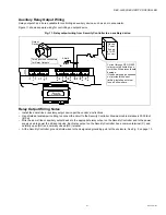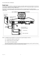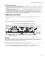
SEC-H-600 SECURITY CONTROLLER
95-7759—07
8
The maximum allowable voltage drop due to wiring is 1.5V.
This equates to the difference in voltage measured across the
PS+ and PS- at the source SEC-ENC-H-1 or SEC-ENC-H-2 enclosure power supply, and the PS+ and PS- at the furthest non-
powered Security Enclosure that houses an expansion module. Or, when powered by battery backup, the difference in voltage
measured across the BB and PS- at the enclosure with the Security Controller, and the BB and PS- at the furthest WEBs-AX
Security Enclosure.
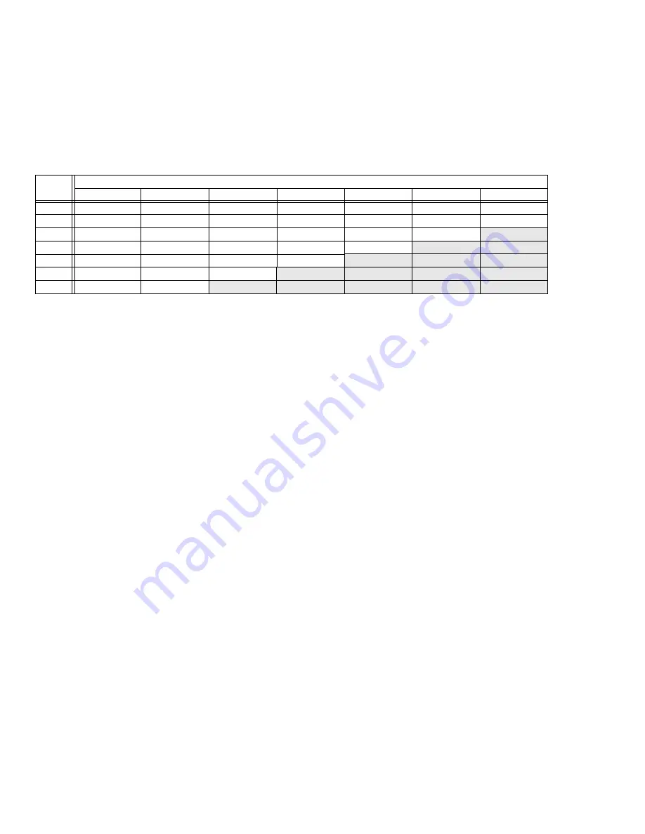
Table 3 provides a voltage drop chart, showing voltage drops per 100 feet of paired wire of different gauges (AWG), at different
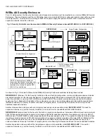
load amps. Also see “Connection Overview” on page 14.
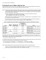
See Table 2 for “worst case” amps used by SEC-H-R2R and SEC-H-RIO modules, using two different reader types (readers draw
either 0.13A or 0.04A each).
For an example, consider in the previous System 2, 10 door readers, that two of the four SEC-H-R2R modules are mounted
remotely in locations 500 feet (366m) away. In this example, worst-case amps used by each remote SEC-H-R2R is 0.33A.
Looking at Table 3 at the 0.25A column, a #16 AWG cable pair drops 0.20V per 100 feet, meaning a 500 foot run would drop
slightly over 1V—this would be a good choice over an #18 AWG cable, which would drop over 2V (above the 1.5V maximum
allowable drop).
Maximum Output Load Considerations
If using multiple
powered
Security Enclosures (SEC-ENC-H-1, SEC-ENC-H-2) to power a large system, and running only battery
backup power from the SEC-H-600 controller (on terminals PS-, BB of the SEC-H-201) to expansion modules in other
enclosures, be aware that the
output load cannot exceed 2.5A.
If the output load exceeds this, a soldered (unreplaceable) 2.5A fuse on the SEC-H-600 controller can blow.
Therefore, large systems that are dependent on battery backup operation may need to have remote expansion modules mounted
in
unpowered
Security Enclosures, where they are powered locally using approved third-party, battery-backed 12Vdc power
supplies. See the “UL Requirements” section “Battery-backed Power Supplies,” page 29, for a listing of approved power supply
models. Related wiring details are in the installation document for expansion modules; see “Related Documentation,” page 5.
PREPARATION
Unpack the Security Controller and inspect the contents of the package for damaged or missing components. If damaged, notify
the appropriate carrier at once and return any damaged components for immediate repair or replacement. See “Returning a
Defective Unit,” page 35. See the following sections below: “Included in this Package” and “Material and Tools Required.”
Included in this Package
Included in this package you should find the following items:
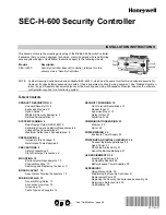
• A Security Controller base controller (SEC-H-600).
• This document,
Security Controller
(
SEC-H-600) Mounting & Wiring Guide
, Form number: 95-7759.
• A hardware bag containing the following items:
— Nine (9) pin-mount, screw-terminal connectors (two 7-position, two 6-position, two 4-position, three 3-position) for con-
nection of security I/O points, sealed lead-acid backup battery. For more details, see “About Screw Terminal Connectors,”
— One (1) grounding wire, with quick-disconnect 0.187" female connector.
— 6 end-of-line resistor packs (four leads each) for installation at contacts wired to supervised inputs.
— One (1) 6-position screw terminal end-plug, for optional wiring of power, battery, and RS-485 communications to another
chain of modules (
not
mounted in-line with the SEC-H-600 controller).
Table 3. Voltage Drop Per 100 Feet Run (30m) of Paired Wire.
Gauge
(AWG)
Load Current
0.10A
0.25A
0.5A
1.0A
1.5A
2.0A
4.0A
10
0.020
0.05
0.10
0.20
0.30
0.40
0.80
12
0.032
0.08
0.16
0.32
0.48
0.64
1.27
14
0.050
0.13
0.25
0.50
0.75
1.01
2.02
16
0.080
0.20
0.40
0.80
1.20
1.60
3.20
18
0.127
0.32
0.64
1.27
1.91
2.54
5.08
20
0.202
0.50
1.01
2.02
3.03
4.03
8.07
22
0.320
0.80
1.60
3.20
4.80
6.40
12.81

