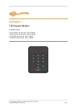
SEC-H-INT-KP SMARTKEY
62-0272—01
2
MOUNTING
Mount the SEC-H-INT-KP backplate onto a wall junction box,
with wiring cable(s) passed through center opening. See
Figure 2 for dimensions.
Fig. 2. SEC-H-INT-KP backplate dimensions.
Fasten with the appropriate screws into the mounting slots.
WIRING
Only two connectors on the back of the SEC-H-INT-KP
(Figure 3) are used: J1 (Power) and J5 (RS-485 comm).
Fig. 3. Connector Detail, Rear View of SEC-H-INT-KP.
Connectors have pre-attached leads—make wiring
terminations to leads using small wire nuts. Lead colors are
shown (in parenthesis) in Figure 3.
CAUTION
Electrical Shock Hazard
Before making wiring terminations, remove power
from the security controller or SEC-H-R2R module.
Restore power only after making all wiring
terminations and fastening the SEC-H-INT-KP
SmartKey unit onto its mounted backplate.
Note that up to 10 SEC-H-INT-KP SmartKey units are
supported, where RS-485 wiring from the security controller
(NPB-2X-485 option card) is “daisy-chained” at the data J5
connector on each SmartKey. For any SmartKey installed on
either end of this RS-485 buss, set its EOL Resistor JUMPER
1 to the ON position.
Wire 12VDC power to the unit from the reader input of the
security controller, or if closer, the reader input of an SEC-H-
R2R module. Use shielded, twisted-pair cabling for all wiring,
with the shield continuously connected and grounded to earth
at one point only. See “Recommended Cable Types,” page 1.
M27320
31/64
(12)
3-5/32 (80)
Ø 1/64 (4)
1-3/16
(30)
2-23/64 (60)
31/64
(12)
5
(127)
2-23/64
(60)
31/64
(12)
31/64
(12)
1
2
3
1
2
3
1
2
3
4
5
1
2
3
1
2
3
1
2
3
4
5
1
2
3
4
1
2
3
5
6
1
2
3
J5
J6
J7
J1
J2
J3
J4
M27321
J5 DATA
(SHIELD) EARTH
(GREEN) DATA (–)
(YELLOW) DATA (+)
J1 POWER
(YEL/GRN) EARTH GND
(BLACK) GND
(RED) + 12V-15 VDC


