background image

Technical Manual 

Sensepoint XCD
Gas Detector

PRE-LAUNCH

Summary of Contents for Sensepoint XCD

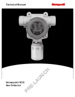
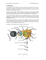
Page 1: ...Technical Manual Sensepoint XCD Gas Detector P R E L A U N C H ...

Page 2: ...htly closed during operation Never attempt to open a junction box enclosure or replace refit the sensor in potentially hazardous atmospheres while power is still applied to the transmitter The detector must be earthed grounded for electrical safety and to limit the effects of radio frequency interference Earth ground points are provided inside and outside the unit The internal grounding shall be u...

Page 3: ...safe practice which could result in severe injury or death to personnel Caution Identifies a hazardous or unsafe practice which could result in minor injury to personnel or product or property damage Note Identifies useful additional information Every effort has been made to ensure the accuracy of this document however Honeywell Analytics can assume no responsibility for any errors or omissions in...

Page 4: ...ation 20 8 Normal Operation 21 8 1 Display Screen 21 8 2 System Status 22 8 3 Magnetic Wand Activation 23 8 4 Operation Mode Structure 23 9 First time switch on Commissioning 24 10 Response Check and Calibration 26 10 1 Zeroing and span calibration 26 10 2 Zeroing and span calibration of Hydrogen Sulfide sensors 29 11 General Maintenance 30 11 1 Operational Life 30 12 Servicing 31 12 1 Sensor repl...

Page 5: ...ing Drawing 51 17 4 Collecting Cone Drawing 52 17 5 Mounting Bolt Assy Drawing 53 17 6 Mounting Bracket Drawing 54 18 Certification 55 18 1 China GB Ex and PA 55 18 2 Korea KTL 58 18 3 European ATEX 59 18 4 International IEC 61 18 5 ATEX Name Plate 63 18 6 UL Name Plate 64 18 7 Sensor Cartridges Label 65 19 Cross Interference and Cross Calibration 66 19 1 Cross Interference Table for Toxic and Oxy...

Page 6: ...ensors a wide range of existing Honeywell Analytics sensors may be used with the Sensepoint XCD transmitter to detect a broader range of target gases please contact Honeywell Analytics for further details The transmitter features a display and three programmable relays for controlling external equipment e g alarms sirens valves or switches The transmitter provides an industry standard 3 wire 4 20m...

Page 7: ...ow which allows use of the Magnetic Wand to activate the three user interface magnetic switches that are located on the front of the display module The magnet also enables a non intrusive one man calibration and configuration facility for the Sensepoint XCD 4 2 Flammable Toxic Oxygen Gas sensors The Sensepoint XCD transmitter is designed to work with a variety of gas sensors for detecting flammabl...

Page 8: ...mmended to be fitted to a Sensepoint XCD sensor for outdoor exposed applications supplied with XCD kit The magnetic wand P N SPXCDMAG is used as a tool to allow the user to communicate with the Sensepoint XCD transmitter for the purpose of configuration calibration and interrogating system status supplied with XCD kit Pipe mounting bracket Gassing Cap The Pipe Mounting Bracket P N SPXCDMTMB is an ...

Page 9: ...ssory that is designed for applications to allow the monitoring for the presence of gas inside a Heating Ventilation or Air Conditioning HVAC duct is required Sunshade Deluge Cover Typical Mounting Arrangement The XCD Sunshade Deluge Cover P N SPXCDSDP is an optional accessory that may be fitted to the integral mounting plate This accessory is designed to protect XCD from overheating in exposed ho...

Page 10: ...re de classify the area or disconnect the equipment from the supply circuit before opening the detector enclosure Keep assembly tightly closed during operation Never attempt to open a junction box enclosure or replace refit the sensor in potentially hazardous atmospheres while power is still applied to the transmitter The detector must be earthed grounded for electrical safety and to limit the eff...

Page 11: ...d equipment involved safety and engineering personnel The agreement reached on the location of detectors should be recorded 5 2 Mounting the transmitter The Sensepoint XCD transmitter has an integral mounting plate consisting of four mounting holes on the transmitter body The transmitter may be fixed directly to a surface mounting or to a horizontal or vertical pipe structure 40 0 80 0mm 1 6 to 3 ...

Page 12: ...3 Note If the XCD sunshade is to be used then fit the sunshade and the two locking bolts and washers to the M8 x 80 bolts 4 Place the transmitter housing against the mounting position and fit the two U channel mounting bars the other side of the Pipe Structure 5 Secure bolts to the threaded holes of the U channel mounting bars 6 Tighten the four bolts securely but do not over tighten until the tra...

Page 13: ...is designed and constructed as to prevent ignition sources arising even in the event of frequent disturbances or equipment operating faults Only assessed for ATEX for ignition hazards To install the XCD Sensor Cartridge to the XCD Sensor Socket 1 Remove the weather protection if fitted from the sensor 2 Use a 1 5mm Allen key hexagonal wrench included to loosen the Locking Grub Screw on the Sensor ...

Page 14: ...s atmosphere de classify the area or disconnect the equipment from the supply circuit before opening the detector enclosure Keep assembly tightly closed during operation Never attempt to open a junction box enclosure or replace refit the sensor in potentially hazardous atmospheres while power is still applied to the transmitter The detector must be earthed grounded for electrical safety and to lim...

Page 15: ...e by removing the display module during installation commissioning see section 9 Caution All electrical connections should be made in accordance with any relevant local or national legislation standards or codes of practice Note Terminate cable screen at detector or controller not both Controller VE Signal 1 2 3 Detector VE Signal VE RL VE 1 3 2 Controller VE Signal 1 2 3 Detector VE Signal VE RL ...

Page 16: ... Display Module is fully engaged in the Display Module Connector on the Terminal Module Diagram 7 Terminal module 15 Terminal Block Power Signal Display Module Connector Display Module Alignment Pin Locator Ground Earth Point Terminal Block for Relays Sensor Connector Note Terminal Blocks are plug socket type and may be removed to ease wiring 1 2 3 4 5 6 7 8 9 10 11 12 13 14 15 Table 1 Transmitter...

Page 17: ...voltage is I P V 5 0 16 312 5mA I detector So the maximum field cable loop resistance R loop 8 0 31 26 Ohms or 13 Ohms per core allowing for component variations losses etc The following tables show the maximum cable distances between the controller and transmitter assuming a voltage drop of 4V in each core and for different cable parameters The tables are examples only and actual cable parameters...

Page 18: ...with a suitable certified sealing plug one plug is supplied 6 5 Cable and Earth Ground regimes Effective Earth Ground bonding is important to ensure good EMC and RFI immunity The following diagrams show examples of how to earth ground bond the cable at enclosures The same principles apply to conduit installations These bonding techniques provide good RFI EMC performance Earth ground loops must be ...

Page 19: ...ilize the shield of the wiring cable recommended in the wiring instructions For connection to this terminal Twist the shield wire to avoid stray shield wires Loosen the screw sufficiently and wrap the wire around the screw in a U shape Raise the clamp and place the wire between the clamp and ground base lower the clamp and tighten the screw to 6 9lb in torque External Ground Connection If required...

Page 20: ...en Signal output inhibited during menu use If any relay is set to inhibit relay then inhibit relay will be activated Timeout Disabled No inhibit timeout The detector waits for a button press before returning to the previous state setting Timeout period can be set in Configure Inhibit menu in Configuration Mode Password 0000 Disabled 0000 Password disabled If changed then password is activated Loca...

Page 21: ...h hi intensity multi colour LED indicator to show NORMAL ALARM and FAULT status During normal operation the instrument display shows a steady GREEN backlight During Low and High Gas Alarm it displays a flashing RED backlight During Fault condition the instrument display shows a flashing YELLOW backlight The screen is visible through the window of the transmitter s cover The display shows the gas c...

Page 22: ...t icon blinking Dependent on system status Green Steady Normal 0 0 Gas concentration 4 20 mA Green Steady Alarm 1 Gas concentration 1st alarm icon blinking 4 20 mA Red flashing Alarm 2 Gas concentration 2nd alarm icon blinking 4 20 mA 1 Red flashing Over range Full scale icon and reading blinking 22mA 2 Red flashing Inhibit Inhibit icon dependent on Menu command If any relay is set to inhibit rela...

Page 23: ...ructure Sensepoint XCD has 3 operating modes 1 Monitoring mode is the normal operating status while XCD measures and displays gas concentration The fault warning status is periodically checked relay contacts are activated according to the configuration 2 Configuration mode this mode allows parameters relating to the configuration of the Transmitter functions to be changed according to specific nee...

Page 24: ...le and Cover Note Ensure that none of the wires in the terminal area cause an obstruction when refitting the Display Module Ensure that the socket on the Display Module is fully engaged in the Display Module Connector on the Terminal Module 8 Switch On external power to the detector 9 All the display icons text numbers are displayed for 3 seconds 10 A start up sequence will then be displayed simil...

Page 25: ...p procedure For the CO sensor version Note For a full description of each screen shown in Diagram 15 please refer to Section 13 3 Review Mode of this Manual 11 The warm up countdown of 60 seconds depending on the gas type is then displayed 12 Normal Monitoring Mode is then resumed ...

Page 26: ...o 1 0 H2S 0 5 to 1 0 CO 0 5 to 1 0 H2 0 5 to 1 0 Flammable IR 0 4 to 0 6 CO2 IR 0 4 to 0 6 A compressed air cylinder 20 9 Vol oxygen should be used to perform the zero calibration if the area where the detector is located contains any residual amount of the target gas If no residual gas is present then the background air can be used to perform the zero calibration Contact your Honeywell Analytics ...

Page 27: ... The display will indicate the first configuration mode menu SEt CAL 4 Put the magnet over the switch again and move to enter the Calibration menu 5 The display will show the current gas reading and the icon flashes 6 When the zero gas reading is stable use to confirm zero calibration 7 If successful the display shows ZEro PASS if not successful the display shows ZEro FAIL and returns to configura...

Page 28: ...live gas reading is displayed When the reading is stable use to confirm span calibration 15 If the sensor has been replaced the following display may be shown 16 Use to select YES if the sensor has been replaced or No if it has not been replaced 17 If the span calibration is successful the instrument will briefly display SPAn PASS if fails SPAN FAIL displayed and returns to configuration mode Note...

Page 29: ...dity changes A sudden increase in ambient humidity can result in a short term positive drift in the instrument s reading A sudden decrease in ambient humidity can result in a short term negative drift in the instrument s reading These are most likely to be noticed during calibration with dry or cylinder gas When calibrating Hydrogen Sulphide cartridges the following should be taken into account wh...

Page 30: ...smitter when carrying out any work must only be conducted by trained personnel Care should be taken when removing and refitting the Sensepoint XCD plug in Sensor Cartridge to the Sensor Socket so that damage to the connection pins can be avoided Before carrying out any work ensure local regulations and site procedures are followed Appropriate standards must be followed to maintain the overall cert...

Page 31: ...are should be taken when removing and refitting the Sensepoint XCD plug in Sensor Cartridge to the Sensor Socket so that damage to the connection pins can be avoided At the end of their working life replacement electrochemical sensors for oxygen and toxic gas must be disposed of in an environmentally safe manner Disposal should be according to local waste management requirements and environmental ...

Page 32: ...osen the Locking Grub Screw and unscrew the Sensor Retainer 4 Carefully pull the old Sensor from the sensor socket without twisting 5 Fit the new Sensor in its place 6 Calibrate sensor WARNING Ensure that the same Gas Type and Range of Sensor is fitted in place of the old Sensor Care should be taken when removing and refitting the Sensepoint XCD plug in Sensor Cartridge to the Sensor Socket so tha...

Page 33: ...nstallation To replace the Terminal Module use the following procedure 1 Unscrew and remove the Transmitter Cover 2 Lift the handle and un plug and remove the Display Module 3 Unplug the connection terminals and lift them clear of the Terminal Module 4 Unplug the connector for the XCD sensor 5 Loosen and remove the three cross headed screws that secure the Terminal Module to the Transmitter housin...

Page 34: ...ed Make sure that there is no flammable gas in the air and use to clear when within limits F 01 Internal I2C failure Cycle power to detector Replace detector F 02 Cell failure For Toxic replace sensor For Flammable IR cycle power to detector Replace sensor F 03 Significant zero drift Re zero calibrate F 04 Unexpected sensor fitted Replace sensor F 05 EEPROM is corrupted Replace sensor F 06 Low sup...

Page 35: ...ailable via the configuration menu that can be displayed on the transmitter and accessed using the Magnetic Wand The instrument will show the main Menu when the Enter switch is activated with the Magnetic Wand and held for at least 3 seconds The Menu is password protected to prevent any unauthorized changes The password is initially disabled and the default password is 0000 If the default password...

Page 36: ... the type of gas from the list This menu is only available for flammable IR sensor Set measuring range Select inhibit current Set timeout option 5 minute increments Enable disable password Set password Default no password Select 0000 Set calibration interval 30 to 365 days User configurable option to display warning Execute a bump test to check gas response of the sensor Force analogue output to t...

Page 37: ...sor Return to Monitoring mode Table 7 Transmitter menu descriptions Diagram 14 Configuration Mode Menu Switch 3 Seconds Monitoring Mode Quit ESC command Auto quit after no activity of timeout Abort Configuration Mode Inhibited Access permitted Inhibit mA O P Yes No Set Calibration Set Range Configure Inhibit Set Password Set Cal Interval Bump Test Force Current Set Alarms Set Relays Relay Operatio...

Page 38: ... ICON DISPLAYED APPLY SPAN GAS AND USE WHEN READING STABLE IF OK PASS PurG DISPLAYED IF FAIL SPAN FAIL DISPLAYED AND RETURNS TO MENU REMOVE SPAN GAS WHEN READING 50 OF SPAN POINT COUNTDOWN BEGINS UNIT RETURNS TO MENU MODE SEt rAn9 BAR GRAPH INDICATING CURRENT RANGE rAn9 DISPLAYED CURRENT RANGE FLASHES USE TO SELECT DIFFERENT RANGE IF RANGE IS CHANGED CAL DISPLAYED AND YES FLASHING TO ASK IF YOU NO...

Page 39: ...O CHANGE TO REQUIRED CONCENTRATION LEVEL AL2 DISPLAYED WITH NonE rISE OR FALL FLASHING USE TO SELECT REQUIRED ALARM ACTION AND USE TO RETURN TO MENU MODE Set rLY rL1 DISPLAYED AND AL1 AL2 Inht or FLt FLASHES USE TO CHANGE TO REQUIRED RELAY TARGET rL1 DISPLAYED AND dEEn or Enr9 FLASHES USE TO CHANGE TO REQUIRED RELAY ACTION Rl2 DISPLAYED AND AL1 AL2 Inht or FLt FLASHES USE TO CHANGE TO REQUIRED REL...

Page 40: ... LEL Catalytic 0 100 LEL Selecting will move the operator to the Select Sensor screen The first screen displays the currently configured sensor To select a new mV sensor use to move through the list then use to make the selection or discard the selection and return to menu mode by using abort function If type of sensor is changed calibration prompt will appear to ask if you want to perform calibra...

Page 41: ...ensor is attached to the XCD a user can select the gas from Str1 1 to Str8 8 For more information on star rating please refer to section 19 2 The current configuration of the XCD is displayed and by using the switch to enter SEL gAS menu To select a flammable gas use to move through the list then use to make the selection or abort function to discard the selection and return to menu mode If type o...

Page 42: ...ach review item in Review Mode are shown in the following table Software version SRS version EEP version Gas Measuring range Calibration level Calibration due Alarm 1 Alarm 2 Item name Display Description S W version of transmitter S W version of SRS watch dog EEPROM parameter version Gas type A user selected measuring range Calibration gas level Estimated time to next calibration Alarm settings f...

Page 43: ... transmitter is installed Power voltage Internal Transmitter temperature Maximum concentration detected up to now There is no fault detected Table 8 Transmitter menu descriptions Note Power voltage and internal transmitter temperature may be different from actual value due to measuring accuracy and internal heating components ...

Page 44: ...Measuring Range Calibration Gas Level EEPROM Version 2 second delay 2 second delay 2 second delay 2 second delay Calibration Due 2 second delay Test Result 2 second delay Peak Reading Temperature 2 second delay 2 second delay Gas Type Supplied input voltage 2 second delay Location 2 second delay SRS Version Alarm Setting 2 second delay 2 second delay Abort ...

Page 45: ...9 V V Fixed 20 9 V V 30 0 5 Vol 20 C 4 F 55 C 131 F 19 5V V 23 5V V Hydrogen Sulfide 10 0 to 100 0ppm 50 0ppm 1 0ppm 25 0ppm 50 1ppm 20 C 4 F 55 C 131 F 10 0ppm 20 0ppm Carbon M onoxide 100 to 1 000ppm 300ppm 100ppm 100ppm 30 6ppm 20 C 4 F 55 C 131 F 100ppm 200ppm Hydrogen 1 000ppm only 1 000ppm n a 500ppm 65 25ppm 20 C 4 F 55 C 131 F 200ppm 400ppm Flam m able 1 to 8 20 to 100 LEL 100 LEL 10 LEL 5...

Page 46: ...ed Carbon Dioxide IR 0 2 00 VOL with LM25 M20 Entry Sensepoint XCD transmitter and sensor KIT ATEX IECEx AP 316SS and M20 Entry SPXCDASMFX ATEX IECEx AP approved Methane CAT 0 100 LEL 20 to 100 LEL 10 LEL with 316SS M20 Entry SPXCDASMRX ATEX IECEx AP approved Methane IR 0 100 LEL 20 to 100 LEL 10 LEL with 316SS M20 Entry SPXCDASMO1 ATEX IECEx AP approved Oxygen 25 0 Vol with 316SS M20 Entry SPXCDA...

Page 47: ...1000ppm 100ppm SPXCDXSG1SS Hydrogen 0 1000ppm only SPXCDXSB1SS Carbon Dioxide IR 0 2 00 VOL only Accessories S3KCAL Calibration cap SPXCDCC Collecting cone for use with lighter than air gases SPXCDDMK Duct mounting kit SPXCDHMANEN Hard Copy Manual in English SPXCDMTBR Pipe Mounting bracket inc fixings and hex wrench set SPXCDSDP Sunshade Deluge Protection Spares SPXCDDMT Replacement display module...

Page 48: ...ance where any fault is not found with he the equipment Honeywell Analytics shall not be liable for any loss or damage whatsoever or howsoever occasioned which may be a direct or indirect result of the use or operation of the Contract Goods by the Buyer or any Party This warranty covers instrument and parts sold to the Buyer only by authorized distributors dealers and representatives as appointed ...

Page 49: ...N 1 UL CSA 2 ATEX II 2 GD Ex d IIC Gb T6 Ta 40 C to 65 C Ex tb IIIC T85 C Db IP66 Baseefa08ATEX0222 IECEx BAS 08 0072 3 KTL Ex d IIC T6 16 32Volts DC Pmax 5W Tamb 40 C To 65 C 4 GB PA CCCF III ITEM LIST 1 XCD TRANSMITTER A O2 TOXIC FL TRANSMITTER B TWO M20 or 3 4 NPT CABLE ENTRY 2 XCD SENSOR CARTRIDGE A 316 STAINLESS STEEL SENSOR B O2 TOXIC FLAMMABLE C PART NUMBER DEPENDS ON GAS TYPE 3 WEATHER PRO...

Page 50: ...LY2 NC Relay 11 RLY2 COM Relay 12 RLY2 NO Relay 13 RLY3 NC Relay 14 RLY3 COM Relay 15 RLY3 NO NOTES 1 REFER TO INSTRUCTION MANUAL FOR TECHNICAL DETAILS 2 XCD OPERATING VOLTAGE 16 32Volts DC 5W Max 3 4 20 mA LOOP RESISTANCE TO BE 300 ohms 4 POWER SUPPLY LOOP RESISTANCE TO BE 12 ohm 5 NO TWO EARTH POINTS SHOULD BE CONNECTED VIA SCREEN AND OR CONDUIT SO AS TO AVOID GROUND LOOPS 6 MULTIPLE EARTH POINT...

Page 51: ...al SPXCDHMANEN Issue 2 51 17 3 Duct Mounting Drawing NTS BEN 6 25 2008 A B C D E F Duct Mounting Hole I ITEM LIST 1 DUCT MOUNTING PLATE 1 159 6 279 150 5 906 120 4 724 10 0 394 4 Mounting Hole 100 3 937 164 6 457 37 1 472 12 0 453 ...

Page 52: ...olume 4 68 cm 3 4 The position of feed points split lines and ejectors to be agreed by HAAP before tool production commences Max permissable flash 0 02 5 PTFE SILICONE or STEARAE RELEASE AGENTS must not be used during manufacture 6 The CAD DATA to be used as the master information for producing this component Dimensions on this drawing are for reference only 7 All surfaces to be free from sink mar...

Page 53: ...Sensepoint XCD Technical Manual SPXCDHMANEN Issue 2 53 2 1 BEN 316SS 25 Oct 07 A B C D 1 5 30 8 0Ø 13 120 M8x1 25 6g 8 13 M8x1 25 6H 3 1 2 14 96 8 36 1 98 17 5 Mounting Bolt Assy Drawing ...

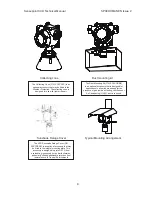
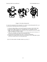
Page 54: ...Sensepoint XCD Technical Manual SPXCDHMANEN Issue 2 54 17 6 Mounting Bracket Drawing ...

Page 55: ...Sensepoint XCD Technical Manual SPXCDHMANEN Issue 2 55 18 Certification 18 1 China GB Ex and PA China GB Ex Chinese Version ...

Page 56: ...Sensepoint XCD Technical Manual SPXCDHMANEN Issue 2 56 China GB Ex English Version ...

Page 57: ...Sensepoint XCD Technical Manual SPXCDHMANEN Issue 2 57 China PA Certification ...

Page 58: ...Sensepoint XCD Technical Manual SPXCDHMANEN Issue 2 58 18 2 Korea KTL ...

Page 59: ...Sensepoint XCD Technical Manual SPXCDHMANEN Issue 2 59 18 3 European ATEX ATEX For Transmitter ...

Page 60: ...Sensepoint XCD Technical Manual SPXCDHMANEN Issue 2 60 ATEX for Sensor ...

Page 61: ...Sensepoint XCD Technical Manual SPXCDHMANEN Issue 2 61 18 4 International IEC IEC Ex for Transmitter ...

Page 62: ...Sensepoint XCD Technical Manual SPXCDHMANEN Issue 2 62 IEC Ex for Sensor ...

Page 63: ...SEP 08 CHANGED NOTES J Y JIN E 16 SEP 08 ADD Certi Numbers J Y JIN NOTES 1 This is an ATEX schedule drawing and can only be changed after approval is given by the certifiying body 2 Serial no format S N SIIPPPYYWWNNN Sequence number Week of MFG Year of MFG Part Code Issue State SUPPLIER CODE 3 Etching Depth 0 1 mm THIS DOCUMENT HAS BEEN GENERATED USDING ADOBE ILLUSTRATOR AND MUST ONLY BE UPDATED B...

Page 64: ...I Division 2 Groups F G Relay Ratings 3x5A 250VAC 2 06 JAN 09 CHANGE SENTENCE J Y JIN before opening Keep tightly closed when in opera tion Conduit runs must have a seal fitting within 18 inches of the enclosure 3 15 JAN 09 CHANGE SENTENCE J Y JIN 4 24 JAN 09 REMOVE CLASS2 J Y JIN 5 27 JAN 09 CHANGE SENTENCE J Y JIN Honeywell Sensepoint XCD Honeywell Analytics Inc Lincolnshire IL USA 60069 Gas Det...

Page 65: ...ONLY BE UPDATED BY A I 3001EA053 3001EA053 Sensor Cartridge Label Artwork Drawing BEN HUR 12 SEP 08 NTS A 12 SEP 08 NEW DRAWING J Y JIN THIS DRAWING IS CONFIDEN TIAL IT IS THE PROPERTY OF HONEYWELL ANALYTICS LTD AND MUST NOT BE REPRO DUCED EITHER WHOOLY OR PARTLY ALL RIGHTS IN RESPECT OF PATENTS DESIGNS AND COPYRIGHT ARE RESERVED APPROVED BY CHANGE DATE ISSUE SCALE REFERENCE PARTNUMBER FINISH TITI...

Page 66: ...lene 100 ppm 0 ppm H2S Hydrogen 100 ppm 0 ppm H2S Hydrogen Sulfide 10 ppm 10 ppm H2S Nitrogen Monoxide 25 ppm 0 ppm H2S Nitrogen Dioxide 3 ppm 0 ppm H2S Sulfur Dioxide 2 ppm 0 ppm H2S CO Acetone 1000 ppm 0 ppm CO Acetylene 40 ppm 80 ppm CO Ammonia 100 ppm 0 ppm CO Carbon Monoxide 100 ppm 100 ppm CO Chlorine 2 ppm 0 ppm CO Ethanol 2000 ppm 3 ppm CO Ethylene 100 ppm 85 ppm CO Hydrogen 100 ppm 20 ppm...

Page 67: ...libration procedure may be followed Notes 1 Table 11 lists a selection of hydrocarbon compounds and states a reference figure or Star Rating according to the reaction they produce in relation to other hydrocarbons 2 An eight star 8 gas produces the highest output while a one star 1 gas produces the lowest output No Gas Star Rating 1 Acetone 4 2 Ammonia 7 3 Benzene 3 4 Butanone 3 5 Butane 4 6 Butyl...

Page 68: ...e used with a calibration gas concentration of 50 LEL Table 12 Calibration span setting 3 If a sensor is to be used to detect a gas other than that for which it was calibrated and there is no intention to use an equivalent calibration gas to re calibrate the sensor then the required correction factor may be obtained from Table 13 The reading shown on the gas detector controller or transmitter disp...

Page 69: ...ok up the star rating for each gas in Table 11 Gas No 14 Ethylene 5 Gas no 18 Methane 6 2 Then look up the span settings for a 50 LEL calibration gas in Table 12 by selecting the row of figures next to the 6 in the calibration gas column Select the figure in the 5 column of the gas to be detected section The figure is 62 3 This means that during re calibration the span gas setting on the gas detec...

Page 70: ...63 Fax 1 847 955 8208 detectgas honeywell com www honeywell com Technical Services HAexpert honeywell com Asia Pacific Honeywell Analytics Asia Pacific 508 Kolon Science Valley I 187 10 Guro Dong Guro Gu Seoul 152 050 Korea Tel 82 0 2 2025 0300 Fax 82 0 2 2025 0329 analytics ap honeywell com Please Note While every effort has been made to ensure accuracy in this publication no responsibility can b...

Reviews: