background image

Technical Manual

Signalpoint Pro

Summary of Contents for SGPTPRXXA1

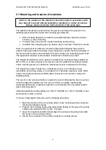
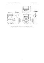
Page 1: ...Technical Manual Signalpoint Pro ...

Page 2: ...BUS OF THE POWER DISTRIBUTION PANEL CONTROLLER RESISTANCE TO GROUND MUST NOT BE GREATER THAN 1 0 OHM ELECTRICAL APPARATUS CONNECTED TO AN INTRINSICALLY SAFE SYSTEM MUST NOT USE OR GENERATE MORE THAN 250V Vrms WITH RESPECT TO EARTH GROUND INSTALLATION MUST BE IN ACCORDANCE WITH THE BARRIER MANUFACTURER S INSTRUCTIONS AND WITH ARTICLE 504 505 IN THE NATIONAL ELECTRIC CODE ANSI NFPA 70 BARRIER ENCLOS...

Page 3: ...rrors or omissions in our documents or there consequences Honeywell Analytics greatly appreciates being informed of any errors or omissions that may be found in the contents of any of our documents For information not covered in this document or there is a requirement to send comments corrections about this document please contact Honeywell Analytics Honeywell Analytics reserve the right to change...

Page 4: ...nd isolators 12 6 5 Cable screening 13 7 Default configuration 14 8 First time switch on 15 8 1 Setting full scale detection range 16 8 2 Changing span calibration point 16 8 3 Calibration 17 8 3 1 Zeroing and span calibration of the toxic version detector 17 8 3 2 Calibrating the Oxygen version detector 18 9 Normal operation 20 9 1 Normal operating display 20 9 2 Detector fault message display 20...

Page 5: ...n industry standard 2 wire IS 4 20mA loop Signalpoint Pro is suitable for connection to a wide range of Honeywell Analytics or 3rd party control equipment 4 1 Product overview The Signalpoint Pro detector is supplied as a toxic or Oxygen transmitter with a separate plug in sensor Diagram 1 Signalpoint Pro explode view 4 1 1 Transmitter Two versions of transmitter are available toxic or Oxygen vers...

Page 6: ...sed Replacement sensors can be simply installed by removing the old sensor and plugging in a new one even with the unit under power 4 1 3 Accessories Calibration gas flow housing The calibration gas flow housing part number SGPTPPCFA is used for calibration or sample flow applications Weatherproof cap A weatherproof cap is available part number 02000 A 1635 to offer additional protection against h...

Page 7: ... MUST BE IN ACCORDANCE WITH THE BARRIER MANUFACTURER S INSTRUCTIONS AND WITH ARTICLE 504 505 IN THE NATIONAL ELECTRIC CODE ANSI NFPA 70 AND OR CANADIAN ELECTRICAL CODE SECTION 18 BARRIER ENCLOSURE MUST MEET REQUIREMENTS OF ANSI ISA S82 FOR USE IN NON HAZARDOUS OR CLASS I DIVISION 2 GROUPS A B C AND D HAZARDOUS LOCATIONS USE A UL LISTED OR NRTL APPROVED DUST TIGHT ENCLOSURE AND CONDUIT FITTINGS APP...

Page 8: ...ee unhindered access to terminals for easy termination of incoming cables A pre drilled 21mm diameter clearance entry LHS and 21mm clearance knockout RHS allow connection via conduit or cable with suitable glands The use of 2 core screened cable is required to prevent false alarms due to sources of electromagnetic interference The use of conduit or suitably mechanically protected cabling and compr...

Page 9: ...MANUAL MAN0853 Issue 3 10 08 8 Diagram 2 Detector dimensions and mounting hole locations 150mm 5 9 105mm 4 1 83 5mm 3 3 72 5mm 2 85 120mm 4 7 Mounting holes M3 5 or No 6 screws 21mm diameter clearance hole 21mm diameter knockout ...

Page 10: ... CODE ANSI NFPA 7 AND OR CANADIAN ELECTRICAL CODE SECTION 18 BARRIER ENCLOSURE MUST MEET REQUIREMENTS OF ANSI ISA S82 FOR USE IN NON HAZARDOUS OR CLASS I DIVISION 2 GROUPS A B C AND D HAZARDOUS LOCATIONS USE A UL LISTED OR NRTL APPROVED DUST TIGHT ENCLOSURE AND CONDUIT FITTINGS APPROPRIATE FOR ENVIRONMENTAL PROTECTION IN CLASS II DIVISION 2 GROUPS F AND G AND CLASS III HAZARDOUS LOCATIONS ACCESS T...

Page 11: ...er 1 2 VE 1 Detector VE VE RL Simple Zener Barrier or Isolator Signal VE 4 2 B A R R I E R Internal Shield Diagram 3 Single barrier schematic 6 1 2 Hazardous Zone 1 or Div 1 installation type 2 Controller 1 2 3 VE Signal 1 2 3 Detector VE Signal VE RL Dual Zener Barrier or Mirror Isolator 4 4 Internal Shield N C Controller 1 2 3 VE Signal 1 2 3 Detector VE Signal VE RL Dual Zener Barrier or Mirror...

Page 12: ...0 The resulting totals should not be greater than the value shown for the barrier or isolator Example using MTL7787 dual channel zener barrier Capacitance permitted by the barrier Cb Inductance permitted by the barrier Ib Internal capacitance of the field device Cf Internal inductance of the field device If Capacitance of the cable per metre Cc Inductance of the cable per metre Ic Total allowable ...

Page 13: ... metre for European Installations Maximum length of cable due to capacitance Ca Cc 0 083 0 0002 415 metres Maximum length of cable due to inductance Ia Ic 3 05 0 00066 4621 21 metres As is often the case capacitance is the most limiting figure and so the maximum cable length will be 415 metres Note Due to circuit limitations do not run cable in excess of 1219metres 4 000ft even if the above formul...

Page 14: ...is suitable for the terminal it is recommended that a short length of wire is crimped to the cable shield braid as shown in the diagram below Note Cable shield pigtail and conductors must be as short as possible Transmitter terminal housing wall Cable shield braid Signal wires Shield wire Crimp Sleeve Diagram 6 Cable screen connection ...

Page 15: ...only 20 9 Vol 20 9 Vol only N A Hydrogen Sulphide 0 15 0ppm 10 0 to 50 0ppm 1 0 10ppm 5 to 30ppm 5 0ppm Hydrogen Sulphide 0 100ppm 50 to 500ppm 10 50ppm 20 to 300ppm 5ppm Carbon Monoxide 0 300ppm 100 to 999ppm 100 100ppm 40 to 600ppm 5ppm Sulfur Dioxide 0 0 15 0ppm 5 0 to 20 0ppm 5 0 7 5ppm 2 0 to 12 0ppm 0 5ppm Ammonia 0 200ppm 50 to 200ppm 50 100ppm 20 to 120ppm 5ppm Ammonia 0 1 000ppm 200 to 1 ...

Page 16: ...n the software version number then the detection range and finally a countdown to 0 Countdown time varies from 30 seconds to 4 minutes depending on the sensor type During this start up sequence the current output will remain at 4mA 9 Once countdown is complete the detector will enter normal operating mode 10 Check the voltages at the transmitter terminals are above the minimum requirement 11 Calib...

Page 17: ...ill exit this mode if no button is pressed within 30 seconds 8 2 Changing span calibration point Each plug in sensor has a default recommended span calibration point For most sensors this point is user adjustable Refer to Section 7 for default span calibration points and adjustable calibration point ranges To set the span calibration point to a new value follow the procedure below 1 Loosen the 2 t...

Page 18: ...wipe by the end of the tESt display the instrument will automatically proceed to the calibration mode 3 The display will indicate CAL and the calibration level 4 The display will then indicate ZEr XXX where XXX is the length of time 30 seconds to 4 minutes dependent on gas type and commence counting down to 0 5 When 0 is reached if the zero is successful the display will show APPLY then GAS If not...

Page 19: ...housing Contact your Honeywell Analytics representative for details of suitable calibration kits Zeroing of the Oxygen version detector does not require user to apply gas Normally the span can be set using background air which contains 20 9 VOL Oxygen If for any reason background air cannot be used then span the detector using a zero air cylinder 300 375mL min flow regulator tubing and calibration...

Page 20: ...if the span calibration is successful the instrument will return to normal operation If not successful Cal Err is displayed and the detector returns to normal operating 8 If using zero air switch off the regulator and remove the calibration flow housing 9 The calibration procedure is complete ...

Page 21: ...g Non latching Orr Sensor overrange Non latching SEn Er0 Excessive negative reading Recalibrate Non latching SEn Err Sensor error Replace sensor Non latching EE Err EEPROM error Contact service center Non latching nO SEnS No sensor is installed Install a sensor Non latching ZEr Err Zeroing error Re zero the unit Non latching CAL Err Calibration error Recalibrate the unit Non latching 9 3 General n...

Page 22: ... power connected is the operation of the Mode and Set switches located on the rear of the front portion of the enclosure when opened Instructions for the operation of these switches is indicated in section 7 Any other Maintenance Service functions needed to be done inside the main housing will require disconnection of power to the instrument The only other live maintenance function allowed is sens...

Page 23: ...librate the detector see instructions in step 6a Otherwise if the accuracy is within acceptable range the instrument should be returned to monitoring mode see instructions in step 6b 6 In either case allow the gas to purge and then exit the test mode by swiping the magnet once over the oval mark during the test mode The instrument then displays rESEt for 15 seconds a To enter the calibration mode ...

Page 24: ...g to stabilise Caution The following procedure should be followed carefully and only performed by suitably trained personnel A fault condition will be signalled by the detector if the sensor is removed with the unit under power WARNINGS See Live Maintenance procedures in section 10 1 prior to performing any Maintenance or Service Take care when handling sensors as they may contain corrosive soluti...

Page 25: ...ode The instrument then displays rESEt for 15 seconds 10 Wait for the instrument to time out of the rESEt display mode and the instrument then enters the calibration mode 11 Recalibrate the detector see step 3 of section 8 3 1 for toxic version or step 3 of section 8 3 2 for Oxygen version Sensor Cover Sensor retaining ring Transmitter Diagram 7 Replacing plug in sensor Sensor ...

Page 26: ...ision 1 Groups A B C D E F G Intrinsically Safe II 2 G Ex ia IIC T4 1 Detection performance is temperature and humidity dependent Listed data is based at 20 C 50 RH only Response time is longer when operating in colder temperatures Based on a 20 25 C temperature 50 to 80 RH using a calibration gas flow housing on a freshly calibrated instrument If different cylinders are used other that the calibr...

Page 27: ... gas flow housing 02000 A 1635 Weatherproof cap including remote gassing nozzle SGPTPRMTL1 Single channel zener barrier MTL7728 SGPTPRMTL2 2 channel zener barrier MTL7787 SGPTPRMTL3 Galvanic Isolator MTL 5042 SGPTPRPFG1 Galvanic Isolator P F KFD2 STC4 EX1 SGPTPRCBLG Hummel cable gland HSK K Ex blue M20x1 5 elongated 15mm Part number 1 291 2002 30 including locking nut Part number 1 262 2001 50 For...

Page 28: ...s or damage caused by accident abuse abnormal operating conditions or poisoning of sensor Defective goods must be returned to Honeywell Analytics premises accompanied by a detailed description of any issue Where return of goods is not practicable Honeywell Analytics reserves the right to charge for any site attendance where any fault is not found with he the equipment Honeywell Analytics shall not...

Page 29: ...trical apparatus for the detection and measurement of combustible gases toxic gases and oxygen ATEX Standard s EN60079 0 2006 Electrical apparatus for Explosive gas atmospheres General Requirements EN60079 11 2007 Electrical apparatus for explosive gas atmospheres Part 11 Equipment Protection by Intrinsic Safety I EN60529 1991 A1 2001 Degrees of Protection provided by Enclosures IP 66 Manufactured...

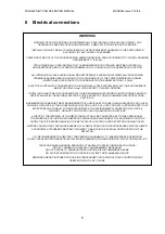
Page 30: ...SIGNALPOINT PRO OPERATING MANUAL MAN0853 Issue 3 10 08 29 16 Control Drawing ...

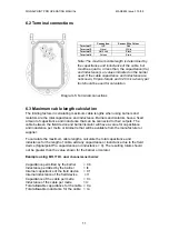
Page 31: ...SIGNALPOINT PRO OPERATING MANUAL MAN0853 Issue 3 10 08 30 ...

Page 32: ...SIGNALPOINT PRO OPERATING MANUAL MAN0853 Issue 3 10 08 31 17 Certification Label ...

Page 33: ...well Analytics Find out more www honeywellanalytics com Europe Middle East Africa India Life Safety Distribution AG Wilstrasse 11 U31 CH 8610 Uster Switzerland Tel 41 0 44 943 4300 Fax 41 0 44 943 4398 gasdetection honeywell com Americas Honeywell Analytics Inc 405 Barclay Blvd Lincolnshire IL 60069 USA Tel 1 847 955 8200 Toll free 1 800 538 0363 Fax 1 847 955 8208 detectgas honeywell com www hone...

Reviews: