® U.S. Registered Trademark
▪
All Rights Reserved.
Copyright © 2010 Honeywell Inc.
MU1B-0441GE51 R0710B
Type SHC
SUPERHEAT CONTROLLER – OEM VERSION
INSTALLATION INSTRUCTIONS
GENERAL
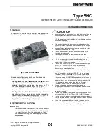
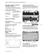
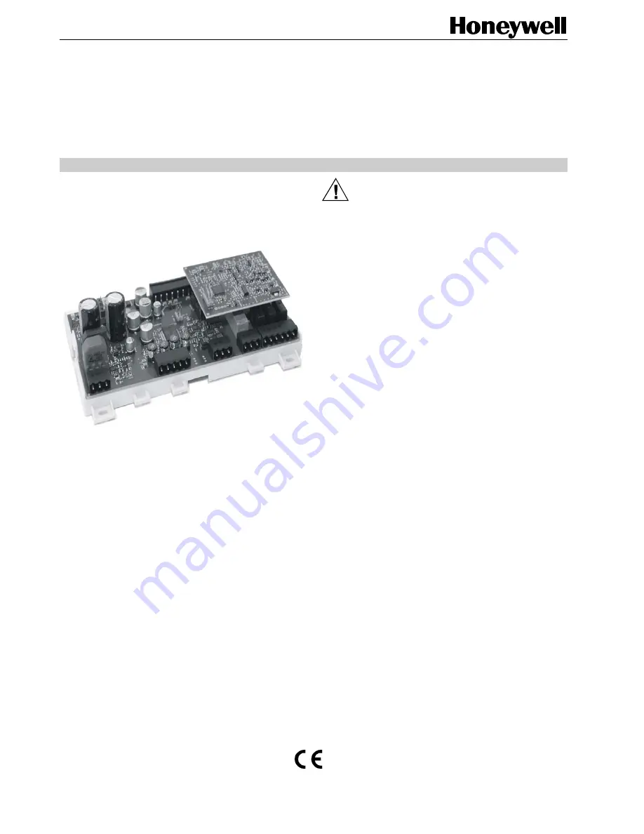
The OEM SHC Controller comes complete with base plate,
main board, plug-in board, and a set of terminal blocks.
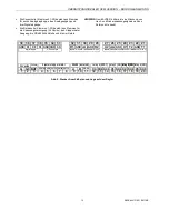
Fig. 1. OEM SHC Controller
There are two configurations to choose from, depending
upon your desired application:
Configuration for Brine-to-Water Heat Pumps
: Control
algorithm for liquid/liquid refrigeration circuit is pre-
selected. Use of Honeywell temperature sensor type TS-
NFR and Honeywell pressure sensor type PSR is
required. Application-specific settings available, upon
request.
Configuration for Air-to-Water Heat Pumps
: Control
algorithm for air/liquid refrigeration circuit is pre-selected.
Use of Honeywell temperature sensor type TS-NFR and
Honeywell pressure sensor type PSR is required.
Application-specific settings available, upon request.
BEFORE INSTALLATION
IMPORTANT
It is recommended that the SHC Controller be kept at
room temperature for at least 24 hours before apply-
ing power; this is to allow the evaporation of any
condensation resulting from low shipping / storage
temperatures.
CAUTION
•
The product may be mounted only by trained personnel who are
thoroughly familiar with all pertinent electrical safety rules.
•
To avoid electrical shock or equipment damage, you must turn
OFF the power supply before attaching / removing connections
to/from any terminals.
•
Do not power the SHC with line voltage!
•
If the product is mounted where unauthorized personnel has
access, the relays may not be used for switching line voltage
(230 Vac).
•
In case of relays switching line voltage, two neighboring relays
may switch the same phase, only.
•
Sensors and secondary (output) of transformer may not be
grounded simultaneously.
•
Grounding of secondary (output) of transformer is
not
recommended.
•
Alarm relay without power must be recognized as “alarm” if used.
•
A 24 V emergency battery module (not included) can be
connected to the SHC to enable safe closing in the event of a
power failure. 1 Ah is recommended.
•
Sensors with current output 4...20 mA and ratiometric voltage
output 0.5 V…4.5 V may not be used simultaneously.
•
Connecting sensors by wires more than 6 m long may decrease
the accuracy of measured values.
•
To prevent damage to the compressor, the signal indicating
whether the compressor is running or not must be connected to
the SHC’s enabler input in case the SHC is in the Automatic
Superheat Control mode while COLD STORE supervision is
disabled. If the SHC is operating in the Automatic Superheat
Control mode and COLD STORE supervision is simultaneously
enabled, the enabler input can be used (e.g., for main power
indication), but it may not be connected with compressor. If the
SHC is operating in any mode other than the Automatic
Superheat Control mode, the enabler input is ignored.
•
If supply voltage has been accidentally applied to the
voltage/current input, wait at least 15 minutes before switching
the SHC ON.
•
Disabling the Low superheat alarm and High superheat alarm is
not
recommended.
•
Possible LOP alarm will be erased automatically when the SHC
enters the MANUAL, REMOTE, or CONFIGURATION mode.
•
A switch or circuit-breaker must be included in the installation; it
must be installed in close proximity to the controller and must be
marked as the disconnecting device for the controller.
•
If one of the supported Honeywell transformers (see section
“Accessories”) is not used to supply the SHC controller, protect
the power input line G using an external 3A type T fuse.

