OEM SHC CONTROLLER – INSTALLATION INSTRUCTIONS
MU1B-0441GE51 R0710B
4
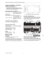
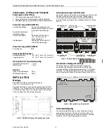
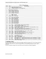
Table 1. Terminal assignment
term. #
name
description
1
G
voltage supply 24 Vac/dc (+)
2
G0
voltage supply 24 Vac/dc (-)
3
BAT
buffer battery module 24 V (+) with power level indicator
4
EARTH earth / shielding
5
OUT2B output 2B of stepped motor
6
OUT2A output 2A of stepped motor
7
OUT1B output 1B of stepped motor
8
OUT1A output 1A of stepped motor
9
A
RS485, A + conductor
10
B
RS485, B - conductor
11
GNDX
RS485, isolated ground
12
C4
relay 4, change-over contact
13
NO4
relay 4, normally-open contact NOC
14
NC4
relay 4, normally-closed contact NCC
15
C1
relay 1, change-over contact
16
NO1
relay 1, normally-open contact NOC
17
C2
relay 2, change-over contact
18
NO2
relay 2, normally-open contact NOC
19
C3
relay 3, change-over contact
20
NO3
relay 3, normally-open contact NOC
21
T1
AIN1:
temperature input 1 (NTC10K, NTC20K, Pt1000)
22
GND
AIN1/2:
ground for temperature inputs 1 + 2
23
T2
AIN2:
temperature input 2 (NTC10K, NTC20K, Pt1000)
24
U1
AIN3:
universal input 1 (NTC10K, NTC20K, Pt1000, 0,5…4,5 V ratiometric, 0…10 V)
25
GND
AIN3/4:
ground for universal inputs 1 + 2
26
V5/15
AIN3/4:
sensor voltage supply for universal inputs 1 + 2
27
U2
AIN3:
universal input 2 (NTC10K, NTC20K, Pt1000, 0,5…4,5 V ratiometric, 0…10 V)
28
R2
AIN6:
current/voltage input 2 (0.5…4.5 V, 0…10 V, 4…20 mA)
29
GND
AIN6:
ground for current/voltage input 2
30
V5/15
AIN5/6:
sensor voltage supply for current/voltage inputs 1 + 2
31
GND
AIN5:
ground for current/voltage input 1
32
R1
AIN5:
current/voltage input 1 (0.5…4.5 V, 0…10 V, 4…20 mA)
33
AO
AO1:
analog output 1 (0…10V)
34
GND
AO1:
ground for analog output 1
35
GND
DI1/2/3:
ground for digital inputs 1 + 2 + 3
36
D3
DI3:
digital input 3 (log.1 = contact open or 24 Vac/dc, log.0 = short-circuit or < 2 Vac/dc)
37
D2
DI2:
digital input 2 (log.1 = contact open or 24 Vac/dc, log.0 = short-circuit or < 2 Vac/dc)
38
D1
DI1:
digital input 1 (log.1 = contact open or 24 Vac/dc, log.0 = short-circuit or < 2 Vac/dc)
39
GND
DI1/2/3:
ground for digital inputs 1 + 2 + 3
LEDs
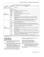
The OEM SHC Controller features three LEDs: a green power LED (LED 1), a red alarm LED (LED 2), and a yellow status LED
(LED 3). The various different possible blinking patterns and the corresponding meanings are listed in Table 2.
After power-up, all of the LEDs are illuminated for a short time during a factory self-test.

