OEM SHC CONTROLLER – INSTALLATION INSTRUCTIONS
MU1B-0441GE51 R0710B
9
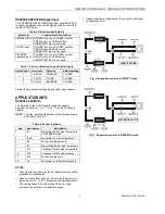
REVERSE OPERATION Digital Input
If the REVERSE OPERATION digital input (terminals 35/36)
is active, the appliance controller signals that the circuit is in
the REVERSE mode.
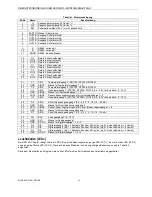
Table 6. Digital Input parameters
parameter
constraints / descriptions
ENABLER input CLOSED: Active on CLOSED contact.
OPEN: Active on OPEN contact.
UNDEFINED: Input is not used.
CLOSE input
CLOSED: Active on CLOSED contact.
OPEN: Active on OPEN contact.
UNDEFINED: Input is not used.
REVERSE
operation input
CLOSED: Active on CLOSED contact.
OPEN: Active on OPEN contact.
UNDEFINED: Input is not used.
Table 7. Factory default settings of digital inputs
digital input
terminals
DI mode
default setting
1
38, 35/39
ENABLER
CLOSED
2
37, 35/39
CLOSE
CLOSED
3
36, 35/39
REVERSE
CLOSED
Further factory default settings are available, upon request.
APPLICATION INFO
Sensor Locations
The firmware of the SHC Controller supports sensors
mounted in positions 1, 3, 6, 7, 9, 14, 17, and 20 defined in
Table 8.
NOTE:
The max. permissible number of connected sensors
at the same time is 6.
Table 8. Sensor locations
pos.
description
description
1
tE1
Evaporator fluid supply temperature
in REVERSE mode
3
tSole1
Evaporator air inlet temperature
6
to2
Suction line temperature
7
to1
Evaporating fluid supply temperature
9
tV2
Condenser fluid supply temperature
14
pV2
Condenser fluid supply pressure
17
po2
Suction line pressure
20
dp
Evaporator air differential pressure
NOTES:
Sensors and secondary (output) of transformer cannot be
grounded simultaneously.
Sensors with current output 4...20 mA and ratiometric vol-
tage output 0.5 V…4.5 V cannot be used simultaneously.
Connecting sensors by wires longer than 6 m might
decrease the accuracy of measured values.
If sensor setting is made wrong, the controller will signal
configuration error.
EEV
CONDENSER
EVAPORATOR
T
M
T
EVAP. FLUID SUPPLY
REVERSE TEMP. (pos. 1)
EVAP. FLUID
SUPPLY TEMP.
(pos. 7)
COND. FLUID SUPPLY
PRESSURE (pos. 14)
EVAP. AIR
SUPPLY TEMP.
(pos. 3)
dP
EVAP. AIR
DIFF. PRESSURE
(pos. 20)
COND. FLUID SUPPLY
TEMP. (pos. 9)
T
SUCTION LINE
TEMP. (pos. 6)
SUCTION LINE
PRESSURE (pos. 17)
T
T
P
P
DIRECT MODE
Fig. 6. Supported sensors in DIRECT mode
CONDENSER
EVAPORATOR
EEV
M
EVAP. FLUID SUPPLY
REVERSE TEMP. (pos. 1)
COND. FLUID SUPPLY
PRESSURE (pos. 14)
COND. FLUID SUPPLY
TEMP. (pos. 9)
T
SUCTION LINE
TEMP. (pos. 6)
SUCTION LINE
PRESSURE (pos. 17)
T
T
P
P
REVERSE MODE
T
EVAP. FLUID
SUPPLY TEMP.
(pos. 7)
EVAP. AIR
SUPPLY TEMP.
(pos. 3)
dP
EVAP. AIR
DIFF. PRESSURE
(pos. 20)
T
Fig. 7. Supported sensors in REVERSE mode

