12
SWIFT® Smart Wireless Integrated Fire Technology Manual —
P/N LS10036-000SK-E:G 4/13/2020
WSK-WGI Wireless System Gateway
Mounting and Wiring
2.7 Mounting and Wiring
2.7.1 Mounting
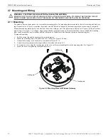
The gateway has two major pieces, the cover and the mounting plate. The mounting plate is mounted to the wall or ceiling, and field wir-
ing is connected to it. The cover contains the printed circuit board and is fastened to the mounting plate once the wiring is completed.
Mount the mounting plate directly to an electrical box on the ceiling or wall. The plate mounts directly to a 4˝ square (with and without
plaster ring), 4˝ octagon, 3 1/2˝octagon, single gang or double gang junction boxes. If an electrical box is not available, the mounting
plate can be mounted to any flat surface and the wiring can be connected via the knockout points in the mounting plate.
To mount the gateway:
1.
Pull the wiring through the opening in the mounting plate.
2.
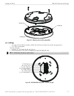
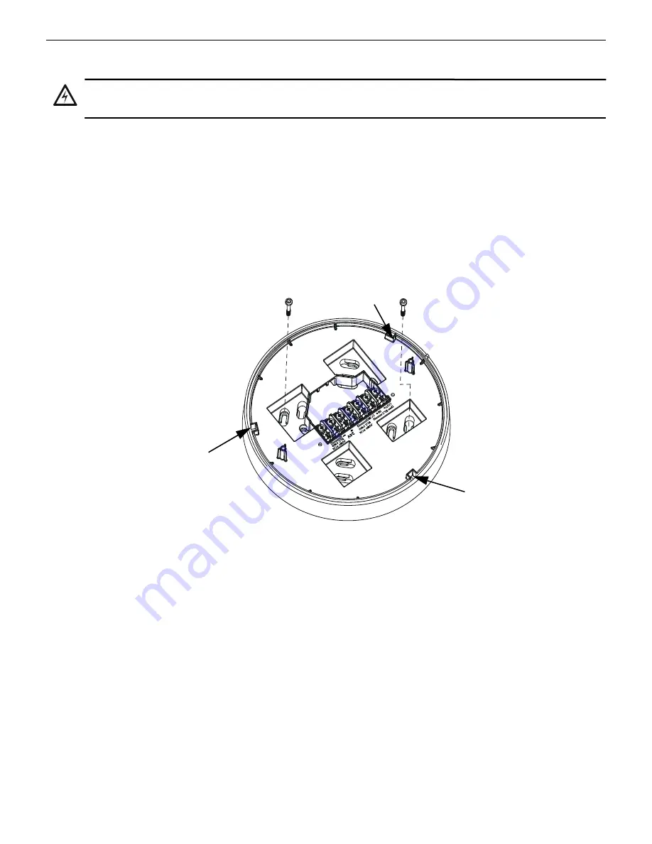
Mount the mounting plate to the junction box or ceiling. See Figure 2.3 below.
3.
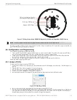
Connect field wiring to the terminals, as described in Section 2.7.2.
4.
Connect necessary jumpers where applicable, as described in Section 2.7.3.
5.
To mount the cover, align the locating pins on the cover to the corresponding slots in the mounting plate. See Figure 2.4.
6.
Secure the cover by tightening the mounting screws.
!
WARNING: POLYPROPYLENE ELECTRICAL INSULATION MATERIAL
ENSURE THAT THE POLYPROPYLENE ELECTRICAL INSULATION MATERIAL COVERING THE PRINTED CIRCUIT
BOARD INSIDE THE GATEWAY IS NOT REMOVED OR TAMPERED WHILE INSTALLING OR CLEANING.
Figure 2.3 Mounting Plate for Wireless Gateway
2.
2
.w
m
f
locating pin
locating pin
locating pin


