SWIFT® Smart Wireless Integrated Fire Technology Manual —
P/N LS10036-000SK-E:G 4/13/2020
53
Appendix D: LED Indicators
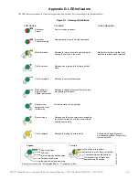
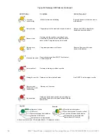
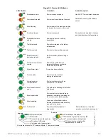
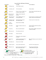
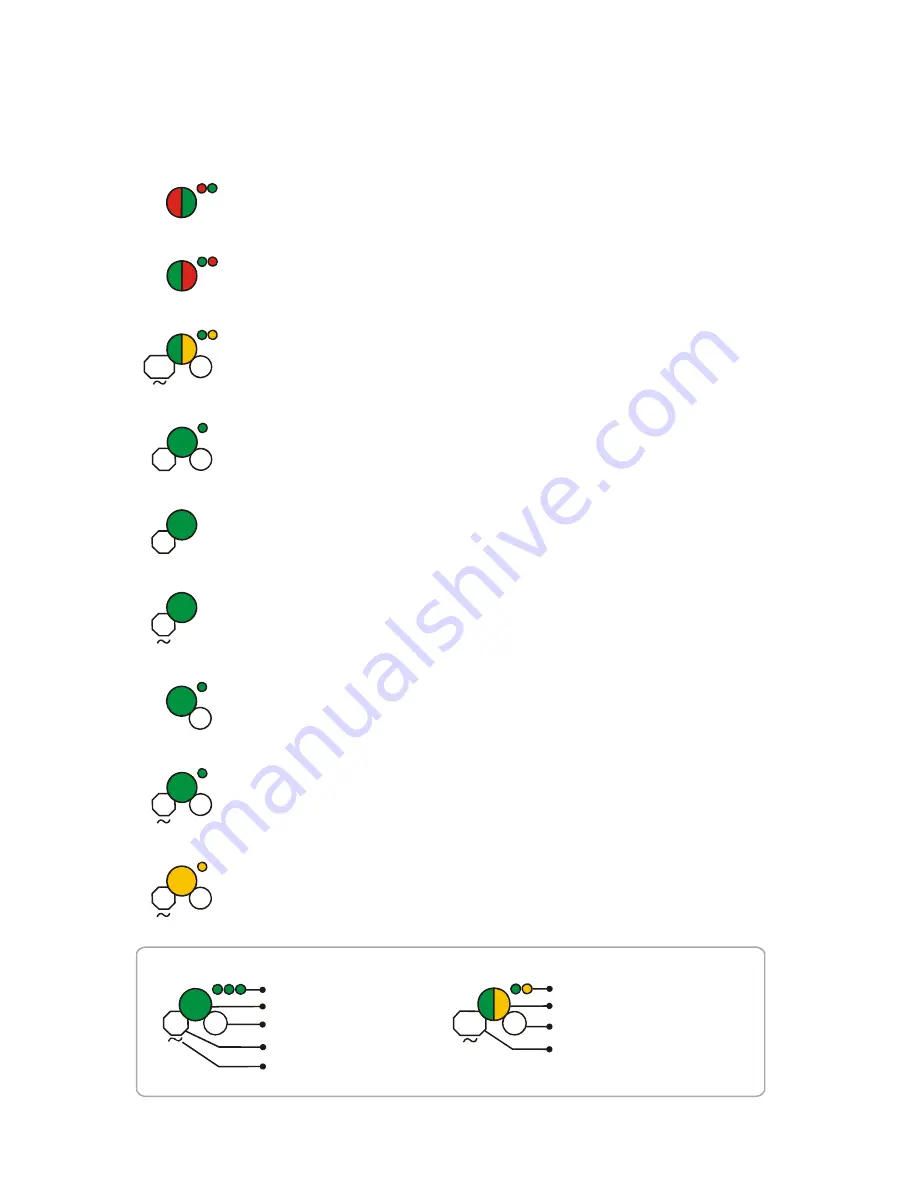
The LED indicator patterns for the wireless gateway and wireless devices are shown in the tables below.
LED Pattern
Condition
Action Required
Bootloader
normal
Bootloader
Firmware update
Mesh formation
Profile removed
Profile accepted
Normal mode/
background mesh
restructuring
Rescue mode
Device is ready to update
New application code is being downloaded
Gateway is forming the mesh and looking for
devices that are not in the mesh
Wait until all devices join the mesh
and then terminate mesh formation
Gateway has returned to the factory default
state
Gateway is now profile assigned
Normal operation of the gateway
Gateway and the mesh network are searching
for any device that is not in the mesh network
with the same profile
Legend
Number of blinks
LED color
Interval between blink patterns
Duration of LED state
Indicates value is approximate
Two blinks in this pattern
First blink is green, Second is yellow
7 seconds between blink patterns
Will transition to next state after
approximately 20 minutes
Example:
All units are in seconds. “M” indicates Minute. “V” indicates Variable.
led
gat
e1_
4.
0.w
m
f
6
20
M
1
5
10
18
12
3
M
Solid
7
20
M
10
1
Profile assigned
Gateway is starting up with a profile
Mesh update in
progress/Mesh
update -parent node
Gateway is updating the mesh/Parent nodes
are updating child nodes
4
M
Solid
Activate both magnetic sensors
simultaneously within 10 seconds to
remove a profile
Figure D.1 Gateway LED Patterns


