SLATE™ LOW TORQUE ACTUATOR SERIES
32M-06009—06
6
1
Do not wire the non-isolated common terminal to the Slate system; leave it unconnected. Instead, wire the
24V- of the actuator supply to Pin 2 of the Slate Sub-Base. If all actuators share the same supply, only one con-
nection is needed.
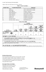
Table 2. Wiring Terminal Identification.
Type
Terminal
Description
Wiring
PE (Protective Earth)
Chassis
ground screw
Chassis connection for mains
power and shield/drain wires
Follow local codes for safety earth
installation. See Electrical installation
section for shield drain installation
instructions.
DC power terminals
24V+
24VDC positive terminal
Shielded twisted pair cable is
recommended. A replaceable 2A fuse
is provided on all actuators. Use a
slow blow fuse if additional external
fusing is desired. Required gauges
are:
Up to 80 ft: 24 AWG
Up to 120 ft: 22 AWG
Up to 500 ft: 16 AWG
Up to 800 ft: 14 AWG
Up to 1200 ft: 12 AWG
24V-
24VDC negative terminal
Low voltage
communication
(Modbus over RS-485)
Industrial models only:
R8001M4050,
R8001M4150
RS485 In+
Isolated RS-485: positive
Shielded twisted pair cable with a
separate common wire is
recommended. See Electrical
installation section for length
limitations. Use 12–24 AWG wire.
NOTE:
Shield should be tied to chas-
sis at Actuator side; do not
connect at SLATE (control-
ler) side.
RS485 In-
Isolated RS-485: negative
RS485COM
Isolated RS-485: common
NOTE:
Must be connected for
reliable performance.
Low voltage
communication
(Modbus over RS-485)
Commercial models
only:
R8001M1050,
R8001M1150
RS485 In+
Non-isolated RS-485: positive
RS485 In-
Non-isolated RS-485: negative
RS485COM
Non-isolated RS-485: common
See note
1

