SLATE™ LOW TORQUE ACTUATOR SERIES
7
32M-06009—06
OPERATING INSTRUCTIONS
The SLATE Actuator is designed specifically for the
SLATE Fuel Air Ratio Module. For actuator operation
and programming information, see the SLATE Fuel Air
Ratio Module document 32-00006 and other SLATE
system documentation (Base Module document 32-
00005, and System Checkout guide 32-00016).
CAUTION
Read instructions carefully.
Read the instruction manual carefully before
initiating the start-up and adjustment
procedure. Verify that all of the equipment
associated with and necessary to the safe
operation of the system has been installed
correctly, that all pre-commissioning checks
have been carried out successfully and that all
safety-related aspects of the installation are
properly addressed.
Overview
SLATE Actuator provides multiple methods for
actuator commissioning, precise closed-loop valve or
damper position control, and health monitoring.
• Position can be commanded via Modbus using the
SLATE Fuel Air Ratio Module.
• Commissioning is accomplished through the
SLATE Fuel Air Ratio Module.
TROUBLESHOOTING
If the two shafts are not perfectly and concentrically
aligned, additional binding and torque will be
introduced into the assembly causing error codes to
be sent from the SLATE actuator to the SLATE Fuel Air
Ratio Module resulting in an inability to properly
commission the system. If you are receiving actuator
error codes either on the SLATE main module or in the
error code register, check the mounting brackets and
coupling's alignment and make necessary
adjustments.
Alarm and lockout event reporting
SLATE alarm and lockout codes are accessed through
the SLATE Fuel Air Ratio Module or using the SLATE
touchscreen display. See documents 32-00013 and
32-00006 for more information.
The Low-Torque Actuators also display status
messages through LED blinks. The LED is on the PCB
inside the unit. These can be used for troubleshooting
purposes.
The cover of the Low-Torque Actuators must be
removed to see the two LEDs:
• Green LED: displays status, including alarm codes
• Yellow LED: displays communication activity
(on RS-485, bus is working and actuator is
communicating with SLATE system)
The normal and error codes are shown in Table 3.
Table 3. Alarm LED Codes.
LED code
Error Characteristic
Action
Continuous Blinking
Normal State – Ready to operate None.
1
Out of range – Actuator is out of
normal operating quadrant
Command actuator to normal operational range.
2
Not calibrated – Actuator not
(Factory) calibrated
Factory calibration data lost; replace actuator.
3
Low Voltage
Check actuator input voltage.
4
High Temperature
Reduce ambient temperature; shield actuator from
heat sources.
5
Mechanical binding, electrical
shorts, or internal electronics
fault.
Check all cables and electrical connections;
check for debris or water on electronics;
check for mechanical binding or slipping;
if persistent, replace actuator.
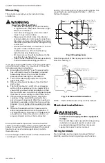
Insure that the shaft key is located in the proper
quadrant (refer to FIG.3). I
f
the shaft key is not
located in this quadrant, manually move the shaft key
to the location per the illustration. Take caution to not
damage the shaft while moving it back into the
functioning quadrant.
5 or Dark Plus
Continuous Reset
Lockout
Check power; replace actuator.

