Honeywell
Parameter Descriptions 57
9
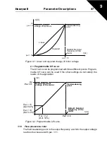
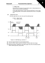
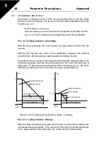
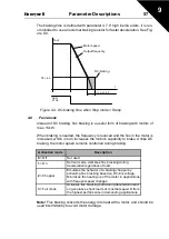
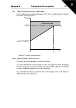
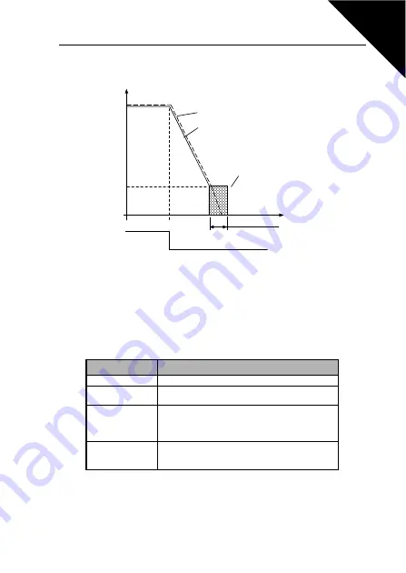
The braking time is defined with parameter 4.7. If high inertia exists, it is rec-
ommended to use an external braking resistor for faster deceleration. See Fig-
ure 9.9.
Figure 9.9: DC-braking time when Stop mode = Ramp
4.8
F
LUX
BRAKE
Instead of DC braking, flux braking is a useful form of braking with motors of
max. 15kW.
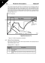
When braking is needed, the frequency is reduced and the flux in the motor is
increased, which in turn increases the motor's capability to brake. Unlike DC
braking, the motor speed remains controlled during braking.
Note!
Flux braking converts the energy into heat at the motor, and should be
used intermittently to avoid motor damage.
Activation mode
Description
0
= Off
Not used
1
= On
Normal mode. Activates flux bracking during
deceleration regardless of load.
2
= Chopper
Emulates the behavior of a braking chopper by
activating flux bracking based on DC-link voltage.
Minimizes the heating up of the motor in applications
with frequent speed changes.
3
= Full mode
Activates flux bracking both during deceleration and
on generative shock loads at constant speed. Offers
the highest performance in demanding applications.
t = par. 4.7
t
Par. 4.6
Motor speed
Output frequency
DC-braking
RUN
STOP
fout

