Honeywell
Parameter Descriptions
69
10
10.7 DIGITAL AND ANALOQUE OUTPUTS (CONTROL PANEL: MENU PAR
-> P7)
7.1
R
ELAY
OUTPUT
1
FUNCTION
7.2
R
ELAY
OUTPUT
2
FUNCTION
(
ONLY
IN
API
FULL
)
7.3
D
IGITAL
OUTPUT
1
FUNCTION
(
ONLY
IN
API
FULL
)
7.4 A
NALOGUE
OUTPUT
FUNCTION
0
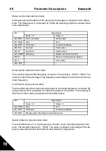
= Full scale
1
= 0 - Max. frequency
2
= 0 - Nominal current
3
= 0 - Nominal torque
4
= PID controller output, 0-100%
7.5 A
NALOGUE
OUTPUT
MINIMUM
0
= 0-20 mA, 0-10V
1
= 4-20 mA, 2-10V
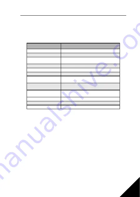
Setting
Signal content
0 =
Not used
Not in operation
1 =
Ready
The frequency converter is ready to operate
2 =
Run
The frequency converter operates (motor is
running, or DC-braking)
3 =
Fault
A fault trip has occurred
4 =
Fault inverted
A fault trip has not occurred
5 =
Alarm
An alarm has occurred
6 =
Reversed
The reverse command has been selected, output
frequency to the motor is negative.
7 =
At speed
The output frequency has reached the set refer-
ence
8 =
Motor regulator activated One of the limit regulators (e.g. current limit, volt-
age limit) is activated
9
= FBControlWord.B13
Modbus control word bit 13
10
= FBControlWord.B14
Modbus control word bit 14
11
= FBControlWord.B15
Modbus control word bit 15
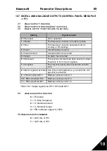
Table 10.2: Output signals via RO1, RO2 and DO1

