background image

SPYDER MODEL 7 VAV CONTROLLER  INSTALLATION INSTRUCTIONS

31-00475-01 

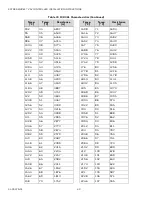
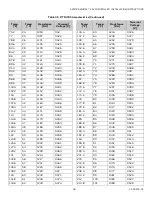
 44

199.4

93

1.4

0.527

251.6

122

0.57

0.225

201.2

94

1.35

0.511

253.4

123

0.56

0.219

203

95

1.31

0.496

255.2

124

0.54

0.213

204.8

96

1.27

0.481

257

125

0.53

0.207

206.6

97

1.23

0.466

258.8

126

0.51

0.201

208.4

98

1.19

0.452

260.6

127

0.5

0.196

210.2

99

1.15

0.439

262.4

128

0.49

0.191

212

100

1.11

0.425

264.2

129

0.47

0.186

213.8

101

1.08

0.413

266

130

0.46

0.181

215.6

102

1.05

0.401

267.8

131

0.45

0.176

217.4

103

1.01

0.389

269.6

132

0.43

0.171

219.2

104

0.98

0.378

271.4

133

0.42

0.167

221

105

0.95

0.367

273.2

134

0.41

0.162

222.8

106

0.92

0.356

275

135

0.4

0.158

224.6

107

0.9

0.346

276.8

136

0.39

0.154

226.4

108

0.87

0.336

278.6

137

0.38

0.15

228.2

109

0.84

0.326

280.4

138

0.37

0.146

230

110

0.82

0.317

282.2

139

0.36

0.142

231.8

111

0.79

0.308

284

140

0.35

0.139

233.6

112

0.77

0.299

285.8

141

0.34

0.135

235.4

113

0.75

0.29

287.6

142

0.33

0.132

237.2

114

0.73

0.282

289.4

143

0.32

0.128

239

115

0.7

0.274

291.2

144

0.32

0.125

240.8

116

0.68

0.266

293

145

0.31

0.122

242.6

117

0.66

0.259

294.8

146

0.3

0.119

244.4

118

0.64

0.252

296.6

147

0.29

0.116

246.2

119

0.63

0.245

298.4

148

0.29

0.113

248

120

0.61

0.238

300.2

149

0.28

0.11

249.8

121

0.59

0.231

302

150

0.27

0.107

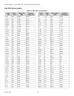
Table 34  20 K NTC Characteristics (Continued)

Temp. 

[°F]

Temp. 

[°C]

Resistance 

[K

Ω

]

Terminal 

voltage [V]

Temp. 

[°F]

Temp. 

[°C]

Resistance 

[K

Ω

]

Terminal 

Voltage [V]

Summary of Contents for Spyder 7

Page 1: ...s 19 SSR DO Wiring Examples 20 20 VDC Auxiliary Wiring Examples 20 Network Concepts 21 The RS 485 Standard 21 TIA EIA 485 Cable Specifications 21 IP Network Topologies 21 Daisy Chain 21 Ring Topology 21 BACnet IP Controller 22 DHCP IP Configuration 22 Link local addressing 22 Static IP Configuration 22 Connect to a IP Network 22 WiFi Future Release 22 Install the Local Antenna 22 Install the Remot...

Page 2: ... 34 Recognition of Sensor Failure of Sensor Inputs 35 Sensor Characteristics 36 10 K NTC TYPE II Characteristics 36 10 K NTC TYPE III Characteristics 38 10 K3A1 Characteristics 39 20 K NTC Characteristics 42 Nickel Class B DIN 43760 Sensors 45 NI1000 TK5000 DIN B 46 PT100 Characteristics 47 PT1000 Characteristics 48 PT3000 Characteristics 54 Abbreviations 55 Related Technical Literature 55 ...

Page 3: ...t effective Spyder Model 7 offers BACnet IP or BACnet MSTP Sylk bus technology Modbus RTU RS 485 universal inputs and output UIO and solid state relays Controller Part Numbers Fig 1 Controller Part Numbers Table 1 Part Numbers Part Number Universal IO Solid State Relay Total IO Communication BLE Integrated WEB VA75IB24NM 7 5 12 IP Yes WEB VA75I24NM 7 5 12 IP No WEB VA00IB24NM 0 0 0 IP Yes WEB VA75...

Page 4: ... INSTRUCTIONS Follow the safety instructions provided by Honeywell in this manual while doing any operation such installation mounting or starting The Spyder Model 7 VAV controllers must be installed and mounted by authorized and trained personnel In the case of any modification except by Honeywell the operation and safety warranties become void Observe all applicable local standards and regulatio...

Page 5: ...nvironment Parameter Specification Storage Temperature 40 F to 150 F 40 C to 66 C Operation 32 F to 122 F 0 C to 50 C Humidity 5 to 95 RH non condensing Protection IP20 NEMA 1 Pollution Level 2 Table 5 Hardware Specification Parameter Specification CPU Crossover processor NXP I MRT Cortex M7 Memory Capacity 16 MB QSPI Flash 16 MB SDRAM Ethernet IP Model only Two each RJ 45 Ethernet ports Real Time...

Page 6: ...ommunication Mode Modbus client only Transmission Mode RTU Remote Terminal Unit Address Range Modbus clients can have an address between 1 and 247 Discrete inputs coils input registers and holding registers can have an address between 1 and 65534 Table 9 Sylk Supported Devices Parameter Specification Sylk wall modules TR40 TR40 H TR40 CO2 TR40 H CO2 TR42 TR42 H TR42 CO2 TR42 H CO2 TR71 TR71 H TR75...

Page 7: ...Minimum duty cycle 50 50 5 ms ON 5 ms OFF The Spyder Model 7 VAV controller has a single common terminal for every two UIOs which protects them against 24 VAC mis wiring and short circuits Table 13 Solid State Relay SSR Specification Solid state relay switches supply voltage and works with 24 20 VAC and 41 VDC VDC switching does not support synchronous motor 1 5 A constant 3 5 A inrush for 0 1 sec...

Page 8: ...721 56 02 86 578 81ආ9 56 ආ13876 2873876 9 8 ආ ආ 5 32 5 25 ආ 9ආ 6 17 11 17 11 6 25 6833257 02 6 ආ3 7 51 7 5 5 ආ 5 3 ආ5 2 6 1625 7 65 1625 TOP VIEW SIDE VIEW BOTTOM VIEW 6 59ආ 87721 6 ඇN 02 8 6 9 32 5 62 ආ 67 7 5 6 665 ආ 5 3 ආ5 2 6 1625 87 87721 56 02 86 578 81ආ9 56 ආ13876 2873876 17 11 17 11 6 25 6833257 02 6 7 5 1625 17 11 25 02 6 56 QHW 0673 ආ 5 3 ආ5 2 6 1625 TOP VIEW SIDE VIEW BOTTOM VIEW 9 8 ආ ...

Page 9: ...dbus and BLE will be erased the IP address will be reset to default and the device will enter DHCP IP configuration Pressing Service Button during normal operation During normal operation of the controller a short press 1 sec of the service button will cause a service button message BACnet WhoAmI as a Private Transfer SerialNo 130 to be sent Refer to the Spyder Model 5 and Spyder Model 7 System En...

Page 10: ...d or have asymmetrical damper shaft mounts If the actuator does not allow any wobble it is likely to bind To prevent this when installing the Spyder Model 7 VAV controllers install it over the damper shaft and then slide the anti rotation bracket underneath and into the mounting slot but not at the very end of the slot Screw the anti rotation bracket using screws on the controller Tools Required P...

Page 11: ...0 3 5 Nm torque d Using the declutch button rotate the universal shaft adapter fully clockwise e Mount the actuator to the VAV damper box and shaft f Tighten the two bolts on the centering clamp 8 mm wrench 70 lb in 8 10 Nm torque g When the actuator closes the damper rotates counterclockwise CCW either 45 or 60 to fully close 3 If the damper rotates counterclockwise CCW to open and the angle of t...

Page 12: ...sing accuracy Use caution when removing tubing from the connector Always pull straight away from the connector or use diagonal cutters to cut the edge of the tubing attached to the connector Never remove by pulling at an angle NOTE Dust particle contamination may be present in some applications Take appropriate steps to limit particulate contamination The sensing element is parallel to the air str...

Page 13: ...nsor is as follows 1 Gently pull the sensor cover outward and rotate it by 75 Fig 12 Removing the Airflow Sensor Cover 2 Disconnect the electrical connector by gently pulling it away from the differential pressure sensor 3 Replace the airflow sensor Fig 13 Replace the Airflow Sensor 4 Attach the electrical connector 5 Close the cover ...

Page 14: ...s for example IEC 364 6 61 or VDE 0100 may take precedence over recommendations pro vide in these installation instructions To comply with CE requirements devices having a voltage of 50 1000 VAC or 75 1500 VDC but lacking a supply cord plug or other means for disconnecting from the power supply must have the means of disconnect incorporated in the fixed wiring This type of disconnect must have a c...

Page 15: ...UIT TO A KNOWN EARTH GROUND UL Listed Class 2 Transformer 100 VA 120 240 VAC 3 2 1 V0 Spyder Model 7 3 2 1 V0 Spyder Model 7 3 2 1 V0 Spyder Model 7 COM 24 VAC Earth Ground 1 UL Listed Class 2 Transformer Field Device Transformer 100 VA 120 240 VAC 3 2 1 V0 AC OUT 5 4 SR IN 8 7 6 Spyder Model 7 COM 24 VAC Earth Ground 1 SR1 C SR2 120 240 VAC M Power Wiring example for one Controller per Transforme...

Page 16: ...minal blocks as follows Strip 1 2 in 13 mm insulation from the conductor Cut a single wire to 3 16 in 5 mm Insert the wire in the required terminal location and tighten the screw If two or more wires are being inserted into one terminal location twist the wires together with a minimum of three turns before inserting them see Fig 15 Cut the twisted end of the wires to 3 16 in 5 mm before inserting ...

Page 17: ... MODEL 7 VAV CONTROLLER INSTALLATION INSTRUCTIONS 17 31 00475 01 Internal Wiring Examples IP Model Internal Wiring Fig 16 IP Model Internal Wiring MSTP Model Internal Wiring Fig 17 MSTP Model Internal Wiring ...

Page 18: ... SSR2 output 9 SR3 SSR3 output 10 C Common 11 SR4 SSR4 output 12 SR5 SSR5 output 13 C Common Sylk 14 WM1 Sylk bus 15 WM2 Sylk bus RS485 16 RS 485 bus for Modbus only 17 RS 485 bus for Modbus only 18 COM Common UIO 19 IO1 Universal signal input output 1 20 C Common 21 IO2 Universal signal input output 2 22 IO3 Universal signal input output 3 23 C Common 24 IO4 Universal signal input output 4 25 IO5...

Page 19: ... Current Input 100 to 100 k e g 20 kNTC PT1000 dry contact contact open collector Ensure correct polarity logic circuit DIGITAL 0 V IO C V V IO IO C IO C IO C S External Power Supply Ensure correct polarity S S S S 0V IN IN 0V 0V IN Output Type Load 0 to 10 VDC 10 mA max 1 k 4 to 20 mA 550 IO C IO IO C Externally Powered minimum wetting current 3 5 mA IO C Voltage Output to Power External Relay En...

Page 20: ...SR4 SR5 C AC OUT SR IN SR1 SR5 Solid State Relay SSR 6 UL Listed Class 2 Transformer Field Devices 100 VA 120 240 VAC 3 2 1 V0 AC OUT 5 4 SR IN 8 7 6 Spyder Model 7 COM 24 VAC Earth Ground 1 1 WHEN CONNECTING POWER TO THE SPYDER MODEL 7 CONTROLLERS CONNECT THE COM LEG OF THE VAC SECONDARY CIRCUIT TO A KNOWN EARTH GROUND SR1 C SR2 M M UL Listed Class 2 Transformer Field Devices 100 VA 120 240 VAC 3...

Page 21: ...22 AWG 1 Pair Shielded Plenum cable is available and meets the BACnet Standard requirements IP Network Topologies Recommended cable CAT5 CAT6 Maximum distance between two controllers or controller and switch should be less than 328 ft 100 m Daisy Chain In the daisy chain connection type if any of the devices in the network fails the devices beyond the failed device also fail Suppose there are 10 d...

Page 22: ...82 for more information on configuring the IP address Connect to a IP Network Spyder Model 7 BACnet IP VAV controller communicates over wired IPV4 network using Ethernet connection via one of two RJ45 ports WiFi Future Release The Spyder Model 7 VAV controllers have a local rubber antenna included in the packaging If the Spyder Model 7 VAV controllers are mounted inside a cabinet or enclosure and ...

Page 23: ...des of the antenna towards the device it is communicating with Fig 26 Remote Antenna Placement Keep the antenna away from devices that cause wireless interference such as other WiFi networks and telecommunications equipment Do not install the antenna close to the floor Fig 27 Remote Antenna Placement The local antenna can be used when the Spyder Model 7 controller is installed in a plastic cabinet...

Page 24: ...ices a maximum of three repeaters can be used Termination Resistors Matched terminating resistors are required at each end of a segment bus wired across and Use matched precision resistors rated W 1 80 130 Ω Ideally the value of the terminating resistors should match the rated characteristic impedance of the installed cable For example if the installed MSTP cable has a listed characteristic impeda...

Page 25: ...ntity of the next client on the BACnet MSTP bus and to which it must pass the token The polling process includes searching for new clients with MAC addresses lying between their own MAC address and that of the next client The property Max Master specifies the highest allowable address for client nodes Max Master is set to 126 by default which means that it can support up to 124 BACnet MSTP VAV con...

Page 26: ...ed to a WEBs N4 station The user can change the device instance number Connect to the BACnet MSTP Network The controller communicates via its BACnet MSTP interface with other BACnet MSTP capable devices for example other room controllers or MSTP controllers Consider the following factors before connecting Maximum BACnet MSTP bus length See Table 18 on page 24 Daisy chain topology Must conform to T...

Page 27: ...page 21 It Should not extend beyond a single building Default Modbus values Cables and Shielding Use shielded twisted pair cable J Y St Y 4 x 2 x 0 8 and connect the Modbus shield to a noise free earth ground only once per Modbus network Shielding is especially recommended when the Modbus cable is installed in areas with expected or actual electromagnetic noise Avoiding such areas is to be preferr...

Page 28: ... safe operation NOTE The firmware version for TR42x wall modules must be 1 00 3 or higher TR70 wall modules are not supported NOTE Shielded cable is recommended if there is a need to reduce the effect of electrical noise Sylk bus Wiring Example Fig 34 Sylk Wiring Topologies Table 22 Recommended maximum distances Single Twisted Pair Non shielded Stranded or Solida Standard Non twisted Thermostat Wi...

Page 29: ...Mobile VAV Balancing app The BACnet instance ID range allows the discovery of additional controllers on the BACnet network For more information about VAV balancing with the HCM mobile app refer to Honeywell VAV Balancing Tools User Guide 31 00472 Table 23 Mobile Application for Balancing Honeywell Connect Mobile HCM is a mobile VAV balancing application that connects to the Spyder Model 7 VAV cont...

Page 30: ...d Modbus LED Status Mode Status Tx and Rx LED Status Visual BACnet Tx1 Fail OFF BACnet Tx1 Success Blinking BACnet Rx1 Fail OFF BACnet Rx1 Success Blinking Modbus Tx2 Fail OFF Modbus Tx2 Success Blinking Modbus Rx2 Fail OFF Modbus Rx2 Success Blinking BACnet Tx1 Rx1 Modbus Tx2 Rx2 BLE Status See Table LED light status Bluetooth LED Status and BACnet and Modbus LED Status below WiFi for future use ...

Page 31: ...n Yellow blinks every 1 s Broken sensor Red permanent ON b Short circuit AutoMac Green blinks every 2 s No Valid Mac Yellow permanent ON Un Ack Alarm Yellow blinks every 2 s Normal operation Green LED permanent ON Communication error Red LED blinks every 200 ms a While performing setpoint balancing using the VAV mobile application the LED pattern changes from static green to red green yellow cycle...

Page 32: ...tement This device complies with Industry Canada license exempt RSS standard s Operation is subject to the following two conditions 1 this device may not cause interference and 2 this device must accept any interference including interference that may cause undesired operation of the device CE Statement The WLAN function for this device is restricted to indoor use only when operating in the 5150 t...

Page 33: ...rmation on substances in articles Any supplier of an article containing a substance meeting the criteria in Article 57 and identified in accordance with Article 59 1 in a concentration above 0 1 weight by weight w w shall provide the recipient of the article with sufficient information available to the supplier to allow safe use of the article including as a minimum the name of that substance On r...

Page 34: ...mselves see Sensor Characteristics on page 36 Table 29 Sensor Accuracies Range Measurement Error Excluding Sensor Characteristics 10 kΩ NTC a 20 k NTC PT3000 NI1000TK5000 b 58 F to 4 F 50 C to 20 C 5 0 K 5 0 K 1 2 K 1 2 K 4 F to 32 F 20 C to 0 C 1 0 K 1 0 K 0 7 K 0 7 K 32 F to 86 F 0 C to 30 C 0 5 K 0 3 K 0 5 K 0 5 K 86 F to 158 F 30 C to 70 C 0 5 K 0 5 K 0 7 K 0 7 K 158 F to 212 F 70 C to 100 C 1...

Page 35: ...ranges the lowest and highest value within the range will be communicated Thus a temperature of 51 F will be communicated as 50 F Table 30 Thresholds for Short circuit SC and Sensor break SB Recognition I O Configuration Measurement Range Recognition Thresholds 2 to 10 V 2 to 10 VDC 4 to 20 mA without pull up SC 1 5 VDC 3 mA SB no recognition 10 k NTC Ω Type II 22 F to 212 F 30 C to 100 C SC 20 Ω ...

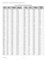
Page 36: ...2 24 122 8 7 534 46 4 8 21 916 4 423 9 4 23 115 72 7 464 48 2 9 20 88 4 316 7 6 22 109 09 7 392 50 10 19 898 4 209 5 8 21 102 88 7 318 51 8 11 18 968 4 103 4 20 97 073 7 241 53 6 12 18 087 3 998 2 2 19 91 597 7 161 55 4 13 17 252 3 894 0 4 18 86 471 7 08 57 2 14 16 46 3 792 1 4 17 81 667 6 996 59 15 15 708 3 69 3 2 16 77 161 6 91 60 8 16 14 995 3 591 5 15 72 932 6 821 62 6 17 14 319 3 492 6 8 14 6...

Page 37: ...49 3 743 1 286 186 8 86 1 039 0 399 122 50 3 603 1 244 188 6 87 1 007 0 387 123 8 51 3 469 1 204 190 4 88 0 976 0 375 125 6 52 3 34 1 166 192 2 89 0 947 0 365 127 4 53 3 217 1 128 194 90 0 918 0 354 129 2 54 3 099 1 092 195 8 91 0 89 0 344 131 55 2 986 1 057 197 6 92 0 863 0 334 132 8 56 2 878 1 023 199 4 93 0 838 0 324 134 6 57 2 774 0 99 201 2 94 0 813 0 315 136 4 58 2 675 0 959 203 95 0 789 0 3...

Page 38: ...31 0 17 8 70 32K 140 60 0 2759 5 15 0 61 02K 145 62 8 2515 10 12 2 53 07K 150 65 6 2296 15 9 4 46 27K 155 68 3 2098 20 6 7 40 42K 160 71 1 1920 25 3 9 35 39K 165 73 9 1759 30 1 1 31 06K 170 76 7 1614 35 1 7 27 31K 175 79 4 1482 40 4 4 24 06K 180 82 2 1362 45 7 2 21 24K 185 85 0 1254 50 10 0 18 79K 190 87 8 1156 55 12 8 16 65K 195 90 6 1066 60 15 6 14 78K 200 93 3 984 65 18 3 13 15K 205 96 1 909 8 ...

Page 39: ... 29 166198 46 4 8 21921 18 4 28 156294 48 2 9 20885 16 6 27 147042 50 10 19903 14 8 26 138393 51 8 11 18973 13 25 130306 53 6 12 18092 11 2 24 122741 55 4 13 17257 9 4 23 115661 57 2 14 16465 7 6 22 109032 59 15 15714 5 8 21 102824 60 8 16 15001 4 20 97006 62 6 17 14324 2 2 19 91553 64 4 18 13682 0 4 18 86439 66 2 19 13073 1 4 17 81641 68 20 12493 3 2 16 77138 69 8 21 11943 5 15 72911 71 6 22 1142...

Page 40: ... 2 49 3741 186 8 86 1037 122 50 3601 188 6 87 1005 123 8 51 3467 190 4 88 974 125 6 52 3339 192 2 89 945 127 4 53 3216 194 90 916 129 2 54 3098 195 8 91 888 131 55 2985 197 6 92 862 132 8 56 2877 199 4 93 836 134 6 57 2773 201 2 94 811 136 4 58 2674 203 95 787 138 2 59 2579 204 8 96 764 140 60 2487 206 6 97 741 141 8 61 2399 208 4 98 720 143 6 62 2315 210 2 99 699 145 4 63 2234 212 100 678 147 2 6...

Page 41: ...109 524 244 4 118 410 230 110 510 246 2 119 399 231 8 111 496 248 120 388 233 6 112 482 249 8 121 378 235 4 113 469 251 6 122 368 237 2 114 457 253 4 123 359 239 115 444 255 2 124 350 240 8 116 432 257 125 341 Table 33 10 K3A1 Characteristics Continued Temp F Temp C Resistance Ω Temp F Temp C Resistance Ω ...

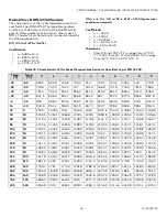
Page 42: ...7 38 2 39 757 8 64 24 8 4 87 3 7 09 36 4 38 706 8 62 26 6 3 82 6 7 01 34 6 37 660 8 6 28 4 2 78 2 6 93 32 8 36 617 8 58 30 2 1 74 1 6 85 31 35 577 8 56 32 0 70 2 6 76 29 2 34 539 8 54 33 8 1 66 5 6 67 27 4 33 505 8 52 35 6 2 63 6 58 25 6 32 473 8 49 37 4 3 59 8 6 49 23 8 31 443 8 47 39 2 4 56 7 6 4 22 30 415 8 44 41 5 53 8 6 3 20 2 29 389 8 41 42 8 6 51 1 6 2 18 4 28 364 8 38 44 6 7 48 5 6 1 16 6 ...

Page 43: ... 11 6 3 06 163 4 73 2 78 0 991 100 4 38 11 1 2 97 165 2 74 2 68 0 96 102 2 39 10 7 2 89 167 75 2 58 0 929 104 40 10 2 2 81 168 8 76 2 49 0 9 105 8 41 9 78 2 72 170 6 77 2 41 0 872 107 6 42 9 37 2 64 172 4 78 2 32 0 844 109 4 43 8 98 2 57 174 2 79 2 24 0 818 111 2 44 8 61 2 49 176 80 2 17 0 792 113 45 8 26 2 42 177 8 81 2 09 0 767 114 8 46 7 92 2 34 179 6 82 2 02 0 744 116 6 47 7 6 2 27 181 4 83 1 ...

Page 44: ...0 162 222 8 106 0 92 0 356 275 135 0 4 0 158 224 6 107 0 9 0 346 276 8 136 0 39 0 154 226 4 108 0 87 0 336 278 6 137 0 38 0 15 228 2 109 0 84 0 326 280 4 138 0 37 0 146 230 110 0 82 0 317 282 2 139 0 36 0 142 231 8 111 0 79 0 308 284 140 0 35 0 139 233 6 112 0 77 0 299 285 8 141 0 34 0 135 235 4 113 0 75 0 29 287 6 142 0 33 0 132 237 2 114 0 73 0 282 289 4 143 0 32 0 128 239 115 0 7 0 274 291 2 14...

Page 45: ... 929 8 935 1 940 5 14 10 945 8 951 2 956 5 961 9 967 3 972 7 978 2 983 6 989 1 994 5 32 0 1000 1005 5 1011 1016 5 1022 1027 6 1033 1 1038 7 1044 3 1049 9 50 10 1055 5 1061 1 1066 8 1072 4 1078 1 1083 8 1089 5 1095 2 1100 9 1106 6 68 20 1112 4 1118 1 1123 9 1129 7 1135 5 1141 3 1147 1 1153 1158 8 1164 7 86 30 1170 6 1176 5 1182 4 1188 3 1194 2 1200 2 1206 1 1212 1 1218 1 1224 1 104 40 1230 1 1236 1...

Page 46: ...26 8 1031 2 1035 8 1040 3 50 10 1044 8 1049 3 1053 9 1058 4 1063 1067 6 1072 2 1076 8 1081 4 1086 68 20 1090 7 1095 3 1100 1104 6 1109 3 1114 1118 7 1123 4 1128 1 1132 9 86 30 1137 6 1142 4 1147 1 1151 9 1156 7 1161 5 1166 3 1171 2 1176 1180 9 104 40 1185 7 1190 6 1195 5 1200 4 1205 3 1210 2 1215 1 1220 1 1225 1230 122 50 1235 1240 1245 1250 1255 1260 1 1265 1 1270 2 1275 3 1280 3 140 60 1285 5 12...

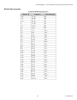
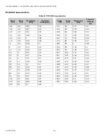
Page 47: ...4 86 20 28 89 89 10 23 33 91 0 17 78 93 10 12 22 95 20 6 67 97 30 1 11 100 32 0 00 100 40 4 44 102 50 10 00 104 60 15 56 106 70 21 11 108 77 25 00 110 80 26 67 110 90 32 22 113 100 37 78 115 110 43 33 117 120 48 89 119 130 54 44 121 140 60 00 123 150 65 56 125 160 71 11 127 170 76 67 130 180 82 22 132 190 87 78 134 200 93 33 136 210 98 89 138 220 104 44 140 ...

Page 48: ...996 0 385 34 6 37 855 0 332 32 0 1000 0 386 32 8 36 859 0 333 33 8 1 1004 0 388 31 35 862 0 335 35 6 2 1008 0 389 29 2 34 866 0 336 37 4 3 1012 0 391 27 4 33 870 0 338 39 2 4 1016 0 392 25 6 32 874 0 339 41 5 1020 0 394 23 8 31 878 0 341 42 8 6 1023 0 395 22 30 882 0 342 44 6 7 1027 0 396 20 2 29 886 0 344 46 4 8 1031 0 398 18 4 28 890 0 345 48 2 9 1035 0 399 16 6 27 894 0 347 50 10 1039 0 401 14 ...

Page 49: ... 107 6 42 1163 0 446 177 8 81 1313 0 501 109 4 43 1167 0 448 179 6 82 1317 0 502 111 2 44 1171 0 449 181 4 83 1320 0 503 113 45 1175 0 451 183 2 84 1324 0 505 114 8 46 1179 0 452 185 85 1328 0 506 116 6 47 1182 0 453 186 8 86 1332 0 508 118 4 48 1186 0 455 188 6 87 1336 0 509 120 2 49 1190 0 456 190 4 88 1339 0 51 122 50 1194 0 458 192 2 89 1343 0 512 123 8 51 1198 0 459 194 90 1347 0 513 125 6 52...

Page 50: ... 0 553 314 6 157 1599 0 603 248 120 1461 0 554 316 4 158 1603 0 605 249 8 121 1464 0 555 318 2 159 1607 0 606 251 6 122 1468 0 557 320 160 1610 0 607 253 4 123 1472 0 558 321 8 161 1614 0 609 255 2 124 1476 0 56 323 6 162 1618 0 61 257 125 1479 0 561 325 4 163 1622 0 612 258 8 126 1483 0 562 327 2 164 1625 0 613 260 6 127 1487 0 564 329 165 1629 0 614 262 4 128 1491 0 565 330 8 166 1633 0 615 264 ...

Page 51: ... 653 451 4 233 1879 0 702 384 8 196 1744 0 655 453 2 234 1883 0 703 386 6 197 1747 0 656 455 235 1886 0 704 388 4 198 1751 0 657 456 8 236 1890 0 705 390 2 199 1755 0 658 458 6 237 1894 0 707 392 200 1758 0 659 460 4 238 1897 0 708 393 8 201 1762 0 661 462 2 239 1901 0 709 395 6 202 1766 0 662 464 240 1905 0 711 397 4 203 1769 0 663 465 8 241 1908 0 712 399 2 204 1773 0 665 467 6 242 1912 0 713 40...

Page 52: ...16 0 749 588 2 309 2152 0 796 521 6 272 2020 0 75 590 310 2156 0 797 523 4 273 2024 0 752 591 8 311 2159 0 798 525 2 274 2027 0 753 593 6 312 2163 0 799 527 275 2031 0 754 595 4 313 2166 0 8 528 8 276 2034 0 755 597 2 314 2170 0 802 530 6 277 2038 0 757 599 315 2173 0 803 532 4 278 2042 0 758 600 8 316 2177 0 804 534 2 279 2045 0 759 602 6 317 2181 0 805 536 280 2049 0 76 604 4 318 2184 0 806 537 ...

Page 53: ...4 8 346 2283 0 84 719 6 382 2408 0 882 656 6 347 2286 0 841 721 4 383 2412 0 883 658 4 348 2290 0 842 723 2 384 2415 0 884 660 2 349 2293 0 843 725 385 2419 0 885 662 350 2297 0 845 726 8 386 2422 0 886 663 8 351 2300 0 846 728 6 387 2426 0 888 665 6 352 2304 0 847 730 4 388 2429 0 889 667 4 353 2307 0 848 732 2 389 2432 0 89 669 2 354 2311 0 849 734 390 2436 0 891 671 355 2314 0 85 735 8 391 2439...

Page 54: ...7 1 35 22 30 3 1 08 167 75 3 91 1 36 13 25 3 05 1 09 176 80 3 95 1 37 4 20 3 09 1 1 185 85 4 1 38 5 15 3 13 1 12 194 90 4 04 1 4 14 10 3 18 1 13 203 95 4 08 1 41 23 5 3 22 1 15 212 100 4 12 1 42 32 0 3 27 1 16 221 105 4 16 1 43 41 5 3 31 1 17 230 110 4 21 1 45 50 10 3 35 1 19 239 115 4 25 1 46 59 15 3 4 1 2 248 120 4 29 1 47 68 20 3 44 1 21 257 125 4 33 1 48 77 25 3 48 1 23 266 130 4 37 1 49 86 30...

Page 55: ...from Honeywell ABBREVIATIONS RELATED TECHNICAL LITERATURE Table 41 Abbreviations Abbreviation Definition SSR Solid State Relay MSTP Multiple Spanning Tree Protocol IP Internet Protocol RTU Remote Terminal Unit BMS Building Management Solutions VAV Variable air volume UIO Universal IO NEMA National Electrical Manufacturers Association SDRAM Synchronous dynamic random access memory QSPI Quad Serial ...

Reviews: