background image

STRYKER VAV ZIO CONFIGURATION

63-2730—01

26

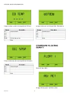
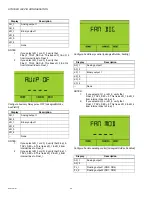
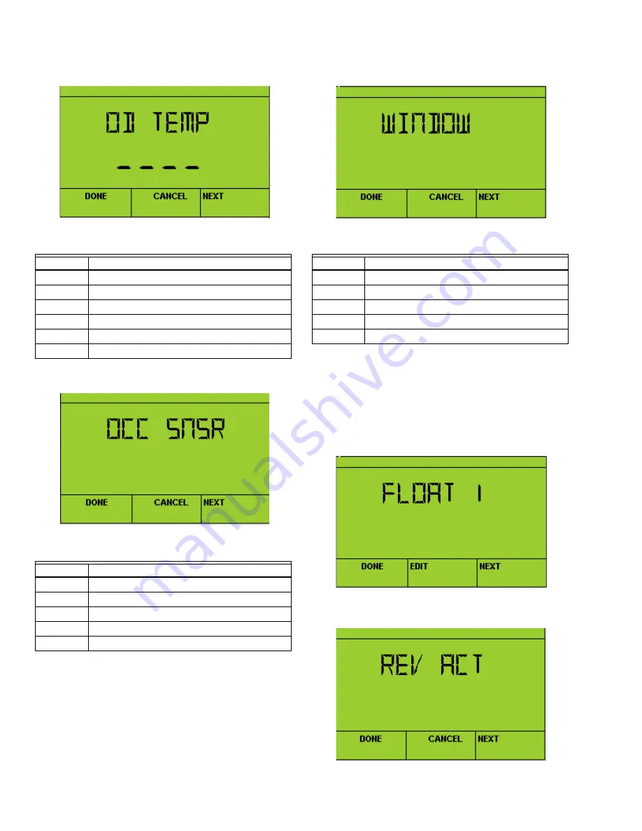
Configure outdoor air sensor [nciLogicalInVav, OdTemp]

Configure occupancy sensor [nciLogicalInVav, OccSensor]

Configure window sensor [nciLogicalInVav, WindowOpen]

CONFIGURE FLOATING 

OUPUT1

Parameter Group Name

Configure floating output 1 [nciFloat1, action]

Display

Description

UI 1

universal input 1

UI 2
UI 3
UI 4
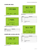
SbUS

C7400s Sbus sensor

--

None

Display

Description

UI 1

universal input 1

UI_2
UI 3
UI 4
--

None

Display

Description

UI 1

universal input 1

UI 2
UI 3
UI 4
--

None

Summary of Contents for Stryker VAV

Page 1: ...tus 9 Temperature Setpoints 10 Override 12 Alarms 13 AirflowBalance 14 Air Flow Configuration 16 Airflow Setpoints 16 Damper Configuration 17 SensorCalibration 18 Wall Module Configuration 19 ControlConfiguration 22 Configure Universal Inputs 24 ConfigureSbus 25 Configure Logical Inputs 25 Configure Floating Ouput1 26 Configure Analog Output 1 2 27 Configure Logical Outputs 28 Standard Zio Configu...

Page 2: ...hat is found in the BALANCE category is manipulating the MaxMeasFlowAct section of the nciBalanceSetPts structured nci and is noted as nciBalanceSetPts MaxMeasFlowAct Values within the Contractor mode are only viewable in English U S units of measure Temperatures however CAN be shown on the home screen as C or F Controller Features NOT Supported by Zio Configuration Network Functionality Accessory...

Page 3: ...or 5 seconds During this time the display will show the model firmware version and Sylk bus address of the TR71 75 Select SetViewMore to add or remove items by choosing YES or NO with the up down buttons Center Setpoint Temperature NOTES 1 The center setpoint can be disabled using Con tractor View WM_CONFG CNTR_SP FALS or true 2 If CNTR_SP FALS the set point can be changed however the value is ign...

Page 4: ... CONFIGURATION 63 2730 01 4 View equipment status data Edit Temperature Setpoints Set overrides for the controller View alarm conditions Edit balancing parameters Edit Flow Configuration parameters Edit Flow Setpoints ...

Page 5: ...r Config for pressure dependent control Calibration of dP Zio and C7400S sensors Wall module configuration Configuration of control parameters Universal input configuration Configure C7400S sensor Configure logical inputs Configure floating output 1 ...

Page 6: ...CONFIGURATION 63 2730 01 6 Configure floating output 2 Configure analog output 1 Configure analog output 2 Configure logical outputs View controller time Set controller time Set controller date Set controller schedule ...

Page 7: ...STRYKER VAV ZIO CONFIGURATION 7 63 2730 01 SENSORS Parameter Group Name View Zio temperature View Zio relative humidity View room temperature View room RH View room CO2 View supply air temperature ...

Page 8: ...ATION 63 2730 01 8 View discharge air temperature View outdoor air temperature View box airflow cfm only View Flow Pressure un calibrated in Pascals View calibrated pressure inWC only View Occ Sensor status View Window switch ...

Page 9: ...URATION 9 63 2730 01 EQUIPMENT STATUS Parameter Group Name View damper position View airflow setpoint View reheat valve position View number of reheat stages on View periph heat valve position View number of periph stages on ...

Page 10: ... limit setpoint shift View auxiliary output status View fan status View modulating fan status TEMPERATURE SETPOINTS Parameter Group Name Set occupied cooling setpoint nciTempSetpoints occupiedCool Set occupied heating setpoint nciTempSetpoints occupiedHeat ...

Page 11: ...at Set standby cooling setpoint nciTempSetpoints standbyCool Set standby heating setpoint nciTempSetpoints standbyHeat View center or set Setpoint Temperature Value range limited by WM_CONFG CNTSP_HI CNTSP_LO Set freeze protection setpoint heating setpoints is changed to this value when window sensor is open nciSpSpcFrz View effective setpoint which displays in F or C ...

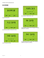
Page 12: ...amper open closed nviFlowOverride state Set fan On Off nviFan state Set modulating Fan Speed nviFan value Reheat override as a percent number of stages or modulation nviValveOvrd reheatPos Peripheral Heat override as a percent number of stages or modulation nviValveOvrd periphPos ...

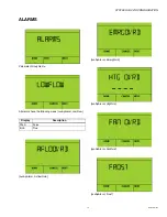
Page 13: ... 63 2730 01 ALARMS Parameter Group Name All alarms have the following views nvoApAlarm LowFlow nvoApAlarm AirflowOvrd nvoApAlarm EmergOvrd nvoApAlarm HtgOvrd nvoApAlarm FanOvrd nvoApAlarm Frost Display Description FALS False trUE True ...

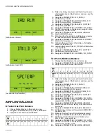
Page 14: ... Min Max Balance 1 Change the Wall Module to the contractor view 2 Navigate to PARAMETERS FLO_CNFG AREASQFT 3 Verify the correct duct Area AREASQFT 4 Obtain the factory zone terminal K factor from the man ufacturer data sheet If the K factor is unknown use the value 1400 5 Navigate to PARAMETERS FLO_CNFG K 6 Set the factory K factor 7 Navigate to PARAMETERS AIRFLOSP MIN_FLO 8 Verify the value of M...

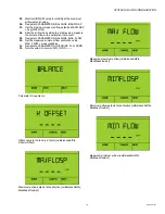
Page 15: ...avigate to PARAMETERS BALANCE MAX_FLOW 30 Set the measured minimum flow calibration value MAX_FLOW measuredValue 31 Navigate to PARAMETERS OVERRIDE FLO_OVRD 32 Return system to normal FLO_OVRD Parameter Group Name Offset value to the factory K factor nciBalanceSetPts KFactorOffset Maximum airflow setpoint at calibration nciBalanceSetPts MaxMeasFlowSpt Measured maximum airflow nciBalanceSetPts MaxM...

Page 16: ...r Group Name Pressure Dependend Flow nciFlowLoop PressDependent Area of duct in square feet nciDuctArea K Factor listed on side of VAV box nciKFactor AIRFLOW SETPOINTS Parameter Group Name Unoccupied flow setpoint in CFM nciMinFlowSetpt Display Description FALS False trUE True ...

Page 17: ...nt in CFM nciMinFlowSetpt Maximum occupied flow setpoint in CFM nciMaxFlowSetpt Reheat Flow Setpoint in CFM nciMaxReheatFlow DAMPER CONFIGURATION Pressure Dependent damper configuration Parameter Group Name Unoccupied minimum damper position nciFlowSP UnOcMinFlowPos Standby minimum damper position nciFlowSP StbyMinFlowPos ...

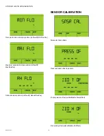
Page 18: ...lowSP MinFlowPos Maximum occupied damper position nciFlowSP MaxFlowPos Reheat damper position nciFlowSP ReheatFlowPos SENSOR CALIBRATION Parameter Group Name Pressure sensor offset in pascals Zio temperature offset nciWallModZio TempOffset Zio humidity offset nciWallModZio RhOffset ...

Page 19: ...Display Home screen temp in F or C nciWallModZio TempUnits Choose wall module type nciWallModCom type Ignore or use center setpoint setpoint can still be changed from home screen but will be ignored nciWallModCom UseWmStPt Display Description nOnE No Wall Module tr20 Conventional Wall Module ZIO Zio Wall Module Display Description FALS Ignore center setpoint True Use center setpoint ...

Page 20: ...low limit nciWallModCom LowSetPt Bypass time in minutes nciWallModCom BypassTime Maximum heating setpoint nciWallModCom MaxHtgSetPt Minimum heating setpoint nciWallModCom MinHtgSetPt Maximum cooling setpoint nciWallModCom MaxClgSetPt Minimum cooling setpoint nciWallModCom MinClgSetPt Effective heating high limit ...

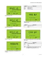
Page 21: ... Module Override Button nciLogicalInVav WallModOvrdBut Conventional Wall Module SetPoint Input nciLogicalInVav SpcTempSP NOTE The TR20 setpoint input is limited to UI_3 Use the Wizard Tool if you require UI_1 2 4 Display Description Stnd Standard Bypass bYPS Bypass Only dSbl Override disabled Display Description dI 1 digital input 1 UI 1 None Display Description UI 3 universal input 3 TR20 210 Zio...

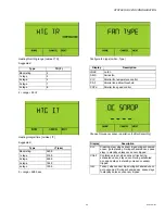
Page 22: ...tion UI_1 universal input 1 UI_2 UI_3 UI_4 210 TR71 or TR75 Wall Module none Display Description CLG cooling only 1 rH 1 stage reheat 2 rH 2 stage reheat 3 rH 3 stage reheat A rH analog mod reheat Display Description rH 0 reheat only P rH 1 peripheral then reheat rH P 2 reheat then peripheral rP A 3 reheat peripheral then reheat airflow PrPH 4 peripheral only Display Description FALS Constant airf...

Page 23: ...lay Description nOnE no fan SErS Series fan P tC Parallel fan temperature control P AF Parallel fan airflow threshold PSPd Parallel fan speed control Display Description CLn Cleaning crew when sensor trips during scheduled unocc go to standby During scheduled occ space stays in standby unless occ sensor tripped COnF Conference room when sensor trips during scheduled unocc stay unocc During schedul...

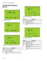
Page 24: ...20 Conventional Wall Module ntc temperature sensor Display Description ntC 20 Kntc temperature sensor dGnO Digital Normally Open dGnC Digital Normally Closed tr_t TR20 Conventional Wall Module ntc temperature sensor Display Description ntC 20 Kntc temperature sensor dGnO Digital Normally Open dGnC Digital Normally Closed trAb TR20 Conventional Wall Module absolute 55 to 85F setpoint input trrL TR2...

Page 25: ...INPUTS Parameter Group Name Configure discharge air sensor nciLogicalInVav DschrgAirTemp Configure supply air sensor nciLogicalInVav SplyTemp Display Description EnbL Enable sensor dSbL Disable sensor Display Description UI 1 universal input 1 UI 2 UI 3 UI 4 SbUS C7400s Sbus sensor None Display Description UI 1 universal input 1 UI 2 UI 3 UI 4 SbUS C7400s Sbus sensor None ...

Page 26: ...nfigure window sensor nciLogicalInVav WindowOpen CONFIGURE FLOATING OUPUT1 Parameter Group Name Configure floating output 1 nciFloat1 action Display Description UI 1 universal input 1 UI 2 UI 3 UI 4 SbUS C7400s Sbus sensor None Display Description UI 1 universal input 1 UI_2 UI 3 UI 4 None Display Description UI 1 universal input 1 UI 2 UI 3 UI 4 None ...

Page 27: ...re floating output 2 nciFloat2 action Actuator travel time as a value in seconds nciFloat2 travelTime A value of zero disables the floating actuator and frees DO_1 DO_2 CONFIGURE ANALOG OUTPUT 1 2 Parameter Group Name AO2 settings are identical Configure analog output 1 nciAO1 analogRng Display Description FALS Direct Action trUE Reverse Action Display Description FALS Direct Action trUE Reverse A...

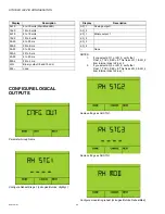
Page 28: ...at_1_TRVL_SEC 0 This frees dO_3 dO_4 from internal links to Float_1 Same settings as RH STG1 Same settings as RH STG1 Configure modulating reheat nciLogicalOutVav ReheatMod Display Description 0d10 0 to 10 volts Wall Mod LED 10d0 10 to 0 volts 2d10 2 to 10 volts 10d2 10 to 2 volts 0A20 0 to 20 ma 20A0 20 to 0 ma 0A22 0 to 22 ma 22A0 22 to 0 ma 4A20 4 to 20 ma 20A4 20 to 4 ma dIG Binary output 0 an...

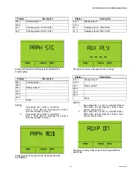
Page 29: ...ct dO_1 or dO_2 verify that Float_2 TRVL_SEC 0 This frees dO_1 dO_2 from internal links to Float_2 2 If you select dO_3 or dO_4 verify that Float_1 TRVL_SEC 0 This frees dO_3 dO_4 from internal links to Float_1 Configure Auxiliary Relay pulse ON nciLogicalOutVav AuxPlsOn Display Description AO_1 Analog output 1 AO_2 FL_1 Floating output 1 DO3 DO4 FL_2 Floating output 2 DO1 DO2 Display Description ...

Page 30: ...rom internal links to Float_1 Configure Fan Binary control nciLogicalOutVav FanDig NOTES 1 If you select dO_1 or dO_2 verify that Float_2_TRVL_SEC 0 This frees dO_1 dO_2 from internal links to Float_2 2 If you select dO_3 or dO_4 verify that Float_1_TRVL_SEC 0 This frees dO_3 dO_4 from internal links to Float_1 Configure Fan Modulating control nciLogicalOutVav FanMod Display Description AO_1 Analo...

Page 31: ... TR2X Wall Module LED nciLogicalOutVav LedMod NOTE AO must be configured 0d10 0 10 volts STANDARD ZIO CONFIGURATION FUNCTIONS Set Time Parameter Group Name Display Description AO_1 Analog output 1 AO_2 FL_1 Floating output 1 DO3 DO4 FL_2 Floating output 2 DO1 DO2 Display Description AO_1 Analog output 1 AO_2 ...

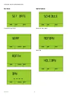
Page 32: ...STRYKER VAV ZIO CONFIGURATION 63 2730 01 32 Set Date Parameter Group Name Set Schedule Parameter Group Name Select Day ...

Page 33: ...STRYKER VAV ZIO CONFIGURATION 33 63 2730 01 Edit Event Time Occupancy State ...

Page 34: ...STRYKER VAV ZIO CONFIGURATION 63 2730 01 34 ...

Page 35: ...STRYKER VAV ZIO CONFIGURATION 35 63 2730 01 ...

Page 36: ...tomation and Control Solutions Honeywell International Inc 1985 Douglas Drive North Golden Valley MN 55422 customer honeywell com U S Registered Trademark 2012 Honeywell International Inc 63 2730 01 M S 05 12 Printed in United States ...

Reviews: