background image


43-TV-33-72    iss.2   GLO  Jan 21   UK 


Before attempting to repair or upgrade a recorder, it is advisable to clear a sufficient work space so components such as 
the front panel can be rested on the work surface without getting scratched or damaged. 


Panel Mounting 

Before a new Inverter can be fitted the recorder must be removed from the panel. Loosen the mounting clamp screws, 
slide the clamp towards the rear of the recorder and remove the clamps and the recorder. 
 

Removing the Touch Screen Assembly 

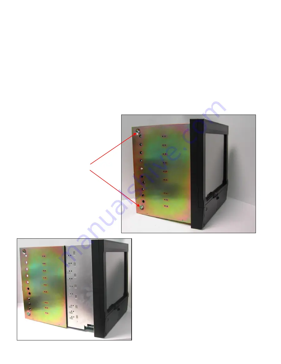
To fit a new Inverter the case and back panel must be removed. The case and back panel can be removed as a single 
assembly. Remove the 2 screws on each side of the case as shown in Fig 1 below 


Slide the case and rear panel assembly off the recorder. 


Fig 1 

Remove 2 screws from 
each side of the case 

Fig 2 

Summary of Contents for SX

Page 1: ...ity WARNING HAZARDOUS VOLTAGES Disconnect all power to the recorder before removing the case and attempting any maintenance procedures SAFETY TESTS Upon completion of service procedures detailed in this manual two basic safety tests should be performed in order to ensure continued safe operation of the instrument Earth Resistance 25 VDC applied between case and protective earth bonding resistance ...

Page 2: ... recorder must be removed from the panel Loosen the mounting clamp screws slide the clamp towards the rear of the recorder and remove the clamps and the recorder Removing the Touch Screen Assembly To fit a new Inverter the case and back panel must be removed The case and back panel can be removed as a single assembly Remove the 2 screws on each side of the case as shown in Fig 1 below Slide the ca...

Page 3: ... the recorder that lock the boards in place Remove the boards by pulling towards the back of the recorder Ensure a note is made of where the boards came from the boards will need to be replaced in exactly the same slots The power supply must also be removed in the same way the securing screw is on the other side of the recorder Fig 3 Power Supply Loosen Screw Withdraw boards Fig 4 Speaker cable Mo...

Page 4: ...ocessor Board See fig 4 above Place the recorder face down ensuring the front face is not going to get scratched or damaged The inverter is now accessible Disconnect the high voltage lead from the inverter See Fig 5 Disconnect the inverter lead from the processor board Undo the two M2 nuts that hold the inverter in place remove the nuts and shakeproof washer Lift the inverter clear of the mounting...

Page 5: ...he connector is polarised so must be fitted in the correct orientation Plug the Mother Board back into the vertical board guides ensure it is properly seated on the processor board Refit all the I O boards and the power supply in the same slots as they originally occupied Tighten up the retaining screws that secure the boards into the chassis Slide the case back onto the recorder ensuring it is fi...

Reviews: