8
107018-04 EN FR26 GLO 1198 Printed in Germany
APPLICATION EXAMPLES (continued)
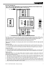
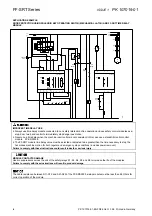
FIG 11. SINGLE CHANNEL EMERGENCY STOP CIRCUITRY (WITH EXTERNAL CONTACTORS)
K4
K5
Start
L1
Honeywell
FF-SRS 5988
Emer-
gency
stop
(A)
N
Y1 Y2
X1 X2
S33
S11
A3
(+)
S34
(B)
K4
K5
Machine Control
K4
K5
Fuses
L2 L3
L1
A4
(-)
(C)
Fuse
Fuses
This circuit has no redundancy in the emergency-stop control circuit and therefore offers a minor
safety level only.
CONTACT REINFORCEMENT VIA EXTERNAL CONTACTORS:
With switching current >10 A, the output contacts should be reinforced by external contactors (K4 and K5)
with positive-guided contacts. (see
note (B)
)
1. After activation of the E-stop push button, the two K2 and K3 LED’s will turn OFF, indicating that the two
internal safety relays K2 and K3 are de-energized. The normally open safety outputs 13/14..63/64 will
open and de-energize the external contactors K4 and K5. The normally closed monitoring output will
also close.
2. After removing the stop condition, press and release the START push button to restart the safety control
module. If the two contactors K4 and K5 are working properly, the K2 and K3 LED’s will turn ON
indicating that the safety relays K2 and K3 are energized. The six normally open safety contacts will
close and the normally closed monitoring contacts will open allowing the machine to operate.
APPLICATION NOTES:
Note (A):
SINGLE CHANNEL SAFETY DEVICES:
This may be a single output safety device such as a safety limit or interlock switch (for example: CLS, GK
and GSS).
Note (B):
EXTERNAL CONTACTORS:
If contact reinforcement via external safety relays is necessary, the output contacts should be reinforced by
external safety relays. The proper operation of the external contactors must be monitored by looping the
NC contacts into the Final Switching Device (FSD) monitoring loop between terminals Y1/Y2.
Note (C):
START MODE:
Manual start mode: Insert start push-button between S33/S34; no jumper must be set between X1/X2
Automatic start mode: Insert jumper between X1/X2
CONTACT MULTIPLICATION VIA EXTERNAL RELAYS
•
If contact multiplication via external safety relays (or the FF-SRE3081 Extension module) is necessary,
connect one normally closed contact of each relay (or 81/82) in series into the Final Switching Device
monitoring loop (terminals Y1/Y2).
•
Use two independent stop circuit safety relays with mechanically linked contacts to reliably detect a welded
contact.
Failure to comply with these instructions could result in death or serious injury.
Summary of Contents for SYA14 Series
Page 2: ...2 107031 23 EN FR26 GLO 1199 Printed in France This page has been left intentionally blank ...
Page 6: ...6 107031 23 EN FR26 GLO 1199 Printed in France This page has been left intentionally blank ...
Page 26: ...26 107031 23 EN FR26 GLO 1199 Printed in France This page has been left intentionally blank ...
Page 62: ...62 107031 23 EN FR26 GLO 1199 Printed in France This page has been left intentionally blank ...
Page 70: ...70 107031 23 EN FR26 GLO 1199 Printed in France This page has been left intentionally blank ...
Page 76: ...76 107031 23 EN FR26 GLO 1199 Printed in France This page has been left intentionally blank ...
Page 78: ...78 107031 23 EN FR26 GLO 1199 Printed in France This page has been left intentionally blank ...
Page 79: ...107031 23 EN FR26 GLO 1199 Printed in France 79 8 CE Declaration of Conformity ...
Page 80: ...80 107031 23 EN FR26 GLO 1199 Printed in France This page has been left intentionally blank ...
Page 84: ......
Page 158: ......
Page 160: ......
Page 161: ...For application help call 1 800 537 6945 Honeywell MICRO SWITCH Sensing and Control 80 ...
Page 165: ...3 107022 14 EN FR26 GLO 0100 Printed in Germany This page has been left intentionally blank ...
Page 201: ...39 107022 14 EN FR26 GLO 0100 Printed in Germany This page has been left intentionally blank ...
Page 205: ...43 107022 14 EN FR26 GLO 0100 Printed in Germany This page has been left intentionally blank ...
Page 207: ...45 107022 14 EN FR26 GLO 0100 Printed in Germany This page has been left intentionally blank ...
Page 208: ...107022 14 EN FR26 GLO 0100 Printed in Germany 46 9 Declaration of Conformity ...
Page 219: ...11 107006 11 EN FR26 GLO 0300 Printed in Germany This page has been left intentionally blank ...
Page 229: ...21 107006 11 EN FR26 GLO 0300 Printed in Germany This page has been left intentionally blank ...
Page 257: ...49 107006 11 EN FR26 GLO 0300 Printed in Germany This page has been left intentionally blank ...
Page 260: ...107006 11 EN FR26 GLO 0300 Printed in Germany 52 9 3 Declaration of conformity ...
Page 340: ...Safety Perimeter Guarding Installation Manual FF SPS4 Series Safety Perimeter Guarding ...
Page 536: ...2 107004 15 EN FR26 ROW 0899 Printed in France This page has been left intentionally blank ...
Page 538: ...4 107004 15 EN FR26 ROW 0899 Printed in France This page has been left intentionally blank ...
Page 542: ...107004 15 EN FR26 ROW 0899 Printed in France 8 This page has been left intentionally blank ...
Page 620: ...86 107004 15 EN FR26 ROW 0899 Printed in France This page has been left intentionally blank ...
Page 624: ...90 107004 15 EN FR26 ROW 0899 Printed in France This page has been left intentionally blank ...
Page 626: ...92 107004 15 EN FR26 ROW 0899 Printed in France This page has been left intentionally blank ...
Page 627: ...107004 15 EN FR26 ROW 0899 Printed in France 93 8 CE Declaration of Conformity ...
Page 628: ...94 107004 15 EN FR26 ROW 0899 Printed in France This page has been left intentionally blank ...


